2007 Silverado Radio Wiring Harness Diagram
Understanding the 2007 Silverado radio wiring harness diagram is crucial for anyone undertaking audio upgrades, repairs, or even just trying to diagnose electrical issues within their vehicle's entertainment system. This article will break down the complexities of the wiring diagram, providing you with the knowledge and confidence to tackle these tasks safely and effectively. It's especially useful if you're bypassing the factory amplifier, installing a new head unit, or need to trace a short circuit.
Purpose of the Radio Wiring Harness Diagram
The radio wiring harness diagram is essentially a roadmap for all the electrical connections associated with your 2007 Silverado's audio system. It serves several vital purposes:
- Repairing Damaged Wiring: Identifying and repairing broken, frayed, or corroded wires. This is especially common after years of use or if rodents have been making a snack of your vehicle.
- Upgrading the Head Unit: When replacing the factory radio (head unit) with an aftermarket one, the diagram is indispensable for connecting the new unit's wiring harness to the vehicle's existing wiring. Improper connections can lead to damage to your new head unit or other electrical problems.
- Installing Amplifiers and Speakers: Adding external amplifiers and/or upgraded speakers requires tapping into the existing audio system. The diagram shows you the speaker wires, remote turn-on wire, and other necessary connections.
- Diagnosing Electrical Issues: If your radio isn't working, or you're experiencing other electrical problems related to the audio system, the diagram can help you trace the circuit and pinpoint the source of the problem.
- Understanding the System: Even if you don't plan on making any modifications, studying the diagram can provide a better understanding of how your vehicle's audio system is wired and how the various components interact.
Key Specs and Main Parts
The 2007 Silverado radio wiring harness involves several key components and specifications to be aware of:
- Head Unit: This is the central control unit, usually mounted in the dashboard. It provides the user interface and handles the processing and distribution of audio signals.
- Wiring Harness: A collection of wires bundled together, connecting the head unit to the vehicle's power supply, speakers, antenna, and other components. These harnesses are often multi-pinned connectors, meaning they have multiple wires connecting into a single plug.
- Speakers: The transducers that convert electrical signals into sound. The Silverado typically has speakers in the front doors, rear doors (depending on the cab configuration), and sometimes tweeters in the A-pillars.
- Antenna: Receives radio signals (AM/FM). The wiring diagram will show the antenna connection to the head unit.
- Ground Wire: Provides a return path for the electrical current, ensuring proper operation. Typically connected to the vehicle's chassis.
- Power Wires: These wires provide the necessary voltage to operate the radio. There are usually two main power wires: a constant 12V (for memory retention) and a switched 12V (activated when the ignition is turned on).
- Data Bus (if applicable): Some Silverado models may use a data bus (like a CAN-BUS system) to communicate between the head unit and other vehicle systems. This is particularly true if the radio is integrated with other functions like OnStar.
- Amplifier (if equipped): Some Silverados came with factory amplifiers. The wiring diagram will show the connections between the head unit, the amplifier, and the speakers. Bypassing or integrating with a factory amplifier adds a layer of complexity.
Understanding the Wiring Diagram Symbols
Wiring diagrams use standard symbols to represent electrical components and connections. Here's a breakdown of some common symbols:
- Solid Lines: Represent wires. Thicker lines may indicate wires with a higher current carrying capacity.
- Dashed Lines: Often indicate shielded wires or connections to ground.
- Circles: Can represent various components depending on the context, such as splices or connection points.
- Squares/Rectangles: Typically represent electrical components like the head unit, amplifier, or other modules.
- Ground Symbol: A series of horizontal lines that indicate a connection to ground.
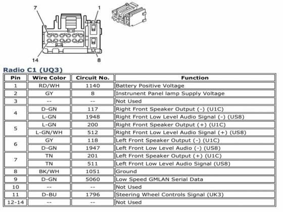
- Wire Colors: Each wire is labeled with a color code (e.g., RED, BLU, GRN). These codes are crucial for identifying the correct wires. Some wires might have stripes, indicated by a slash and another color (e.g., RED/WHT for red with a white stripe).
- Pin Numbers: Each wire connection on a connector is identified by a pin number. This helps you pinpoint the exact location of the wire within the connector.
Important Note: Always refer to the specific wiring diagram for your 2007 Silverado model year, as there may be slight variations depending on the trim level and options.
How It Works: Signal Flow
The audio signal flow starts at the head unit. The head unit receives input from various sources (radio antenna, CD player, auxiliary input, etc.). It then processes these signals and sends them to the speakers (either directly or through an amplifier). The wiring harness provides the physical connections for these signals to travel.
The power wires supply the head unit with the necessary voltage to operate. The constant 12V wire keeps the memory alive (e.g., station presets), while the switched 12V wire turns the unit on and off with the ignition. The ground wire provides a return path for the electrical current.
If the vehicle has a factory amplifier, the head unit typically sends a low-level audio signal to the amplifier. The amplifier then boosts the signal and sends it to the speakers. The remote turn-on wire from the head unit tells the amplifier when to turn on. In some cases, the amplifier might use the CAN-BUS data to determine when to activate.
Real-World Use: Basic Troubleshooting
Here are some basic troubleshooting tips using the wiring diagram:
- No Power to Radio: Check the fuses related to the radio. Use a multimeter to verify that the constant 12V and switched 12V wires are receiving power. If not, trace the wiring back to the fuse box or ignition switch, using the diagram as a guide.
- No Sound from Speakers: Check the speaker wires for continuity using a multimeter. Make sure the speaker wires are properly connected to the head unit or amplifier. If using an aftermarket amplifier, verify that the remote turn-on wire is properly connected. If bypassing a factory amplifier, be sure you've connected the input and output speaker wires correctly.
- Distorted Sound: Check for loose or corroded speaker wire connections. Make sure the speakers are not damaged. If using an amplifier, check the gain settings.
- Radio Turns On but No Display: This could be a problem with the head unit itself. Check the wiring to the display panel.
Remember to always disconnect the negative terminal of the battery before working on any electrical components.
Safety Considerations
Working with automotive electrical systems can be dangerous. Here are some key safety precautions:
- Disconnect the Battery: Always disconnect the negative terminal of the battery before working on any electrical components. This prevents accidental short circuits and potential electrical shocks.
- Identify High-Current Wires: Be especially careful when working with the main power wires (constant 12V and switched 12V). These wires carry a high current, and shorting them can damage the vehicle's electrical system or even cause a fire.
- Use a Multimeter: A multimeter is an essential tool for diagnosing electrical problems. Use it to check for voltage, continuity, and resistance.
- Proper Insulation: Ensure that all wire connections are properly insulated to prevent short circuits. Use heat shrink tubing or electrical tape.
- Work in a Well-Lit Area: Good lighting is essential for seeing the wiring diagram and the actual wiring in the vehicle.
- Refer to the Service Manual: The wiring diagram is a guide, but always refer to the vehicle's service manual for specific instructions and precautions.
Be careful when working around the airbag system. Disconnecting the battery should prevent accidental deployment, but consult a professional if you are uncomfortable. Mishandling airbag wiring can result in serious injury.
The 2007 Silverado radio wiring harness diagram is an invaluable resource for anyone working on their vehicle's audio system. By understanding the symbols, wire colors, and signal flow, you can confidently tackle repairs, upgrades, and troubleshooting tasks.
We have the complete 2007 Silverado Radio Wiring Harness Diagram available for download. This detailed document will provide you with the specific information you need to work on your vehicle's audio system with confidence and precision. Click here to download the file!