2007 Toyota Camry Air Conditioning System Diagram
Understanding the air conditioning (A/C) system in your 2007 Toyota Camry is crucial for maintaining a comfortable driving experience, diagnosing issues, and potentially saving money on repairs. A detailed A/C system diagram is your roadmap to this complex network of components, refrigerants, and pressures. This article will break down the 2007 Camry A/C system diagram, explaining its purpose, key parts, operational principles, and how you can use it for troubleshooting.
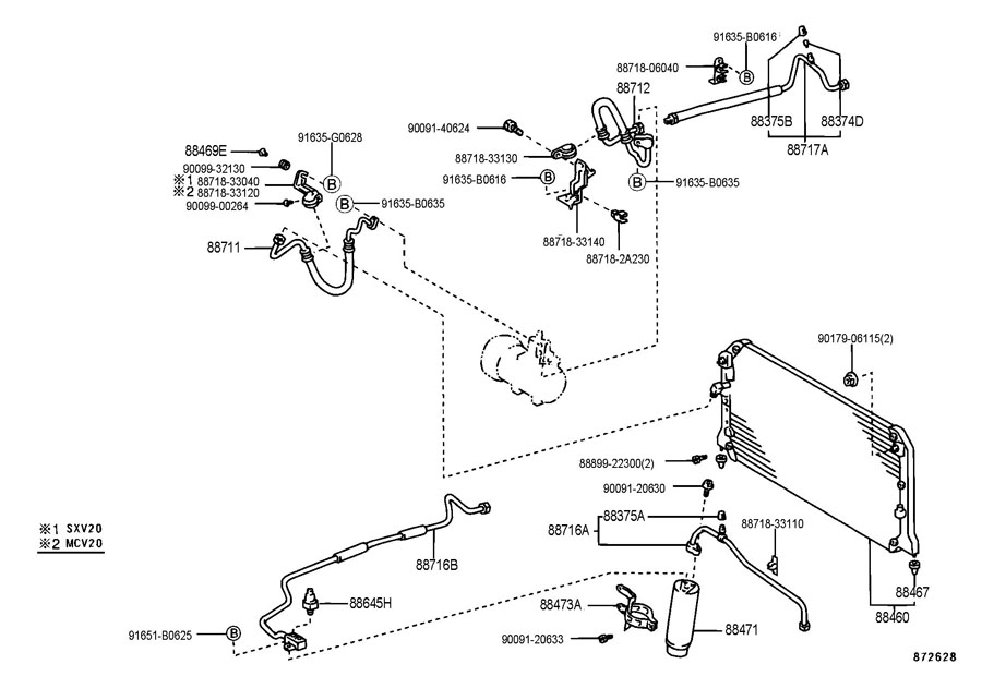
Purpose of the A/C System Diagram
The A/C system diagram serves as a visual representation of the entire air conditioning circuit in your 2007 Camry. It outlines the connections between components, the flow of refrigerant, and electrical connections. This diagram is invaluable for:
- Diagnosis: Identifying faulty components based on symptoms and pressure readings.
- Repair: Guiding the replacement of parts and ensuring correct connections.
- Troubleshooting: Pinpointing the root cause of A/C problems.
- Learning: Understanding the operational principles of the A/C system.
Key Specs and Main Parts
The 2007 Toyota Camry A/C system is a typical automotive A/C system using R-134a refrigerant. Key specs include system capacity (amount of refrigerant) typically found on a sticker under the hood, and operating pressure ranges that vary depending on ambient temperature. Here are the main components:
- Compressor: The heart of the system, the compressor pressurizes the refrigerant, increasing its temperature. This is usually a scroll or reciprocating type compressor driven by the engine via a belt.
- Condenser: Located in front of the radiator, the condenser dissipates heat from the high-pressure, high-temperature refrigerant, causing it to condense into a high-pressure liquid.
- Receiver Drier (or Accumulator): This component filters out moisture and debris from the refrigerant. It also acts as a reservoir for liquid refrigerant. The 2007 Camry uses a receiver drier placed on the high-pressure side (liquid line).
- Expansion Valve (or Orifice Tube): This metering device controls the flow of refrigerant into the evaporator, causing a pressure drop and allowing the refrigerant to expand and cool. The Camry uses an expansion valve.
- Evaporator: Located inside the passenger compartment, the evaporator absorbs heat from the cabin air, cooling it before it's blown through the vents.
- Blower Motor: This fan forces air across the evaporator, circulating cool air into the cabin.
- Pressure Switches: These switches monitor refrigerant pressure and protect the system from damage by shutting down the compressor if the pressure is too high or too low. Important ones include the high-pressure switch and the low-pressure switch.
- A/C Amplifier (Control Module): This electronic module controls the A/C system based on inputs from the temperature control settings, pressure switches, and other sensors.
Symbols and Diagram Conventions
A/C system diagrams use standardized symbols and conventions to represent components and connections. Understanding these is critical for interpreting the diagram:
- Lines: Solid lines typically represent refrigerant lines, while dashed lines usually indicate electrical wiring.
- Arrows: Arrows show the direction of refrigerant flow.
- Component Symbols: Each component has a unique symbol. For example, a compressor might be represented by a circle with a pump symbol inside, while an expansion valve might be a rectangle with a constriction symbol.
- Color Coding (if present): Some diagrams use color coding to distinguish between high-pressure and low-pressure lines. For example, high-pressure lines might be red, while low-pressure lines are blue. However, the 2007 Camry diagram may or may not have color coding, refer to the legend.
- Electrical Symbols: Standard electrical symbols are used for switches, relays, fuses, and other electrical components.
How the A/C System Works
The A/C system operates on the principle of heat transfer through refrigerant phase changes. Here's a simplified explanation:
- Compression: The compressor compresses the low-pressure, low-temperature refrigerant vapor into a high-pressure, high-temperature vapor.
- Condensation: The high-pressure, high-temperature vapor flows to the condenser, where it releases heat to the surrounding air and condenses into a high-pressure, high-temperature liquid.
- Metering: The high-pressure liquid refrigerant flows through the receiver drier and then to the expansion valve. The expansion valve restricts the flow, causing a pressure drop and turning some of the high-pressure liquid refrigerant into a low-pressure liquid and vapor mix.
- Evaporation: The low-pressure liquid/vapor mix enters the evaporator, where it absorbs heat from the cabin air, causing the refrigerant to completely vaporize. This process cools the air that is blown into the cabin.
- Cycle Repeats: The low-pressure, low-temperature vapor returns to the compressor, and the cycle repeats.
Real-World Use: Basic Troubleshooting
The A/C system diagram can be a valuable tool for troubleshooting A/C problems. Here are some basic tips:
- No Cold Air: Check the compressor clutch. If it's not engaging, check the A/C relay and pressure switches. A low refrigerant level can also prevent the compressor from engaging. Use the diagram to locate these components.
- Weak Airflow: Check the blower motor and blower motor resistor. The resistor controls the blower motor speed.
- Strange Noises: Noises can indicate a failing compressor, a bad pulley, or a refrigerant leak. Use the diagram to help you trace the source of the noise.
- Refrigerant Leaks: Look for oily residue near A/C components, which can indicate a leak. Using a UV dye and a blacklight can also help locate leaks.
- Pressure Testing: Connect A/C manifold gauges to the high and low-pressure service ports to check refrigerant pressures. Compare the readings to the manufacturer's specifications. The diagram helps you locate the service ports.
Important Note: When working on the A/C system, always recover the refrigerant before disconnecting any lines. Releasing refrigerant into the atmosphere is illegal and harmful to the environment. You will need specialized equipment for refrigerant recovery and recharging.
Safety Considerations
Working on the A/C system involves handling high-pressure refrigerant, which can be dangerous. Always wear safety glasses and gloves when working on the system.
- Refrigerant Hazards: Refrigerant can cause frostbite if it comes into contact with skin. Avoid direct contact and use proper handling procedures.
- High Pressure: The high-pressure side of the system can reach extremely high pressures. Never disconnect lines or components while the system is pressurized.
- Electrical Hazards: The A/C system includes electrical components, such as the compressor clutch and blower motor. Disconnect the battery before working on these components to avoid electrical shock.
- Professional Help: If you are not comfortable working on the A/C system, seek professional help from a qualified mechanic. Improper repairs can damage the system and lead to costly repairs.
Remember, refrigerant is a controlled substance. Always dispose of it properly and follow local regulations.
We have a detailed 2007 Toyota Camry A/C System Diagram file available for download. This diagram includes detailed schematics and component locations to aid in your diagnostic and repair efforts. This diagram is an invaluable resource for any DIY mechanic or car enthusiast.