
2007 Toyota Camry Exhaust System Diagram
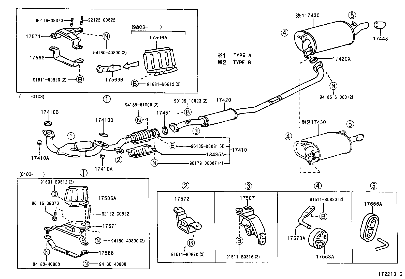
Whether you're tackling a catalytic converter replacement, diagnosing a pesky exhaust leak, or simply deepening your understanding of your 2007 Toyota Camry, having a clear grasp of the exhaust system is essential. This article will break down the 2007 Camry exhaust system diagram, providing you with the knowledge to confidently navigate repairs, modifications, and maintenance. We'll cover the key components, their function, and even some practical troubleshooting tips. Plus, we have the actual diagram available for download to aid you further.
Purpose of Understanding the Exhaust System Diagram
Why bother with a diagram? The exhaust system might seem simple, but it's a complex interconnected network. Understanding its layout is critical for:
- Diagnosis: Pinpointing the exact location of leaks, damaged components, or malfunctioning sensors.
- Repair: Ensuring you order the correct replacement parts and install them correctly.
- Modification: Planning and executing safe and effective aftermarket upgrades.
- General Maintenance: Identifying potential issues before they become major problems.
- Emissions Compliance: Understanding how the system is designed to meet emissions standards.
Key Specs and Main Parts of the 2007 Camry Exhaust System
The 2007 Camry, depending on the engine (2.4L inline-4 or 3.5L V6), has a slightly different exhaust configuration, but the fundamental components remain the same. Here's a breakdown:
2.4L Inline-4 Engine:
- Exhaust Manifold: This is the starting point, bolted directly to the engine cylinder head. It collects exhaust gases from each cylinder. Usually made of cast iron.
- Front Exhaust Pipe (with Catalytic Converter): Connected to the exhaust manifold, this pipe houses the first catalytic converter. The catalytic converter uses a catalyst to reduce harmful emissions (carbon monoxide, hydrocarbons, and nitrogen oxides) into less harmful substances (carbon dioxide, water, and nitrogen).
- Resonator: An optional component found in some models, the resonator helps dampen specific sound frequencies to reduce exhaust noise.
- Mid-Pipe (with Second Catalytic Converter - on some models): Another pipe connecting the front pipe to the muffler. Some models may include a second catalytic converter in this section to further reduce emissions.
- Muffler: The muffler is the final sound dampening device. It uses baffles and chambers to reduce exhaust noise to an acceptable level.
- Tailpipe: The final section of the exhaust system, the tailpipe directs exhaust gases away from the vehicle.
- Oxygen (O2) Sensors: These sensors monitor the oxygen content in the exhaust gases before (upstream) and after (downstream) the catalytic converter(s). They provide feedback to the engine control unit (ECU) to optimize fuel mixture and ensure proper catalytic converter function.
- Exhaust Hangers/Mounts: Rubber or metal mounts that secure the exhaust system to the vehicle's undercarriage, reducing vibrations and preventing damage.
3.5L V6 Engine:
The V6 engine features a dual exhaust system from the manifolds down to, or even through, the mufflers.
- Exhaust Manifolds (Dual): One manifold per cylinder bank.
- Front Exhaust Pipes (Dual, each with Catalytic Converter): One for each manifold.
- Y-Pipe (or Balance Pipe): Combines the exhaust flow from both banks into a single pipe (sometimes located before the catalytic converters). Some models avoid this to retain dual exhaust all the way to the rear.
- Resonator (Optional): May be located after the Y-pipe, or individually on each exhaust branch before they merge.
- Mid-Pipe: Transports exhaust from the Y-pipe/converters to the muffler(s).
- Muffler(s): Either a single muffler with dual inlets, or two separate mufflers.
- Tailpipe(s): Single or dual tailpipes depending on the muffler configuration.
- Oxygen (O2) Sensors: Multiple sensors before and after each catalytic converter on each bank.
Understanding the Symbols in the Diagram
The exhaust system diagram uses standard automotive symbols and conventions:
- Solid Lines: Typically represent exhaust pipes. The thickness of the line might indicate the pipe's diameter.
- Dashed Lines: Often indicate vacuum lines or sensor wiring related to the exhaust system (e.g., oxygen sensor wiring).
- Boxes/Rectangles: Usually represent components like the catalytic converter, resonator, or muffler.
- Circles: Can represent sensors (like oxygen sensors) or connection points.
- Arrows: Indicate the direction of exhaust gas flow.
- Abbreviations: Common abbreviations include "CAT" for catalytic converter, "O2S" for oxygen sensor, and "MAN" for manifold.
- Colors (if present): Colors might be used to differentiate between different pipe sections, materials, or even temperature ranges. However, many diagrams are in black and white.
How the Exhaust System Works
The exhaust system's primary function is to safely and efficiently remove combustion byproducts from the engine. Here's a simplified explanation:
- Exhaust Gases Collection: The exhaust manifold collects hot exhaust gases from each cylinder of the engine.
- Emission Control: The gases pass through the catalytic converter(s), where harmful pollutants are converted into less harmful substances. The efficiency of the converter depends on its operating temperature and the presence of precious metals (platinum, palladium, and rhodium) within its core.
- Noise Reduction: The resonator (if equipped) and muffler work together to dampen sound waves and reduce exhaust noise.
- Safe Disposal: The tailpipe directs the exhaust gases away from the vehicle's occupants.
- Monitoring and Control: Oxygen sensors monitor exhaust gas composition and provide feedback to the ECU, allowing it to adjust the air-fuel mixture for optimal performance and emissions control.
Real-World Use and Basic Troubleshooting
Here are some common exhaust system problems and how the diagram can help:
- Exhaust Leak: Use the diagram to locate potential leak points (joints, welds, flanges). Listen for hissing or popping sounds. Inspect the exhaust system visually for soot deposits, which indicate leaks.
- Catalytic Converter Failure: A clogged or damaged catalytic converter can cause a loss of power and trigger the "check engine" light. The diagram helps you confirm the converter's location and identify the upstream and downstream oxygen sensors.
- Oxygen Sensor Malfunction: A faulty oxygen sensor can cause poor fuel economy, rough idling, and emission failures. The diagram shows the sensor locations and helps you trace the wiring to the ECU.
- Excessive Noise: A loud exhaust can indicate a hole in the muffler or other components. The diagram helps you locate the source of the noise.
Troubleshooting Tip: Remember to always disconnect the negative battery terminal before working on any electrical components, including oxygen sensors.
Safety Considerations
Working on the exhaust system can be dangerous. Here's what to keep in mind:
- Heat: The exhaust system gets extremely hot. Allow the engine to cool down completely before working on it.
- Burns: Wear gloves and eye protection to prevent burns and injuries.
- Exhaust Fumes: Work in a well-ventilated area to avoid inhaling exhaust fumes.
- Jack Stands: Always use jack stands to support the vehicle if you're working underneath it. Never rely solely on a jack.
- Catalytic Converter Risks: Catalytic converters get incredibly hot and contain dangerous chemicals. Allow them to cool completely before handling.
- Oxygen Sensors: Avoid touching the sensor element of an O2 sensor as it can be easily damaged.
Understanding your 2007 Toyota Camry's exhaust system is invaluable for effective maintenance, repair, and modification. By using the diagram in conjunction with these insights, you'll be well-equipped to tackle a wide range of exhaust-related tasks.
We have the detailed 2007 Toyota Camry exhaust system diagram file available for download. Please click the button below to access the file.