
2007 Toyota Sienna Ignition Coil Diagram
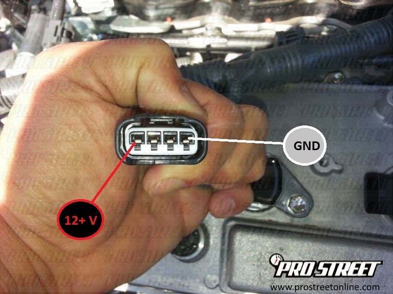
For the seasoned DIY enthusiast or the budding mechanic tackling a 2007 Toyota Sienna, understanding the ignition system is crucial. This article delves into the ignition coil diagram, providing a detailed breakdown of its components, function, and troubleshooting, specifically tailored for the 2007 Sienna. Whether you're replacing a faulty coil, diagnosing engine misfires, or simply expanding your automotive knowledge, this guide will be your trusted companion. We also have the complete ignition coil diagram available for download, which you can access at the end of the article.
Purpose of the Ignition Coil Diagram
The ignition coil diagram is more than just a schematic; it's a roadmap to understanding and repairing your Sienna's ignition system. Its primary purposes are:
- Diagnostics: Identifying potential problems within the ignition system, such as open circuits, short circuits, or faulty components.
- Repair: Guiding the correct replacement of ignition coils, wiring harnesses, and other related parts.
- Troubleshooting: Helping to systematically isolate the root cause of engine misfires, rough idling, or starting problems.
- Learning: Providing a visual representation of how the ignition system functions, enhancing your understanding of automotive electronics.
Without a diagram, you're essentially working blind, increasing the risk of misdiagnosis, incorrect repairs, and potentially damaging other components. Having the diagram available, especially when combined with a diagnostic scanner (OBD II scanner) can reduce your repair time significantly.
Key Specs and Main Parts of the 2007 Sienna Ignition System
The 2007 Toyota Sienna (specifically the 3.5L V6 engine, denoted as the 2GR-FE) utilizes a coil-on-plug (COP) ignition system. This means each cylinder has its own dedicated ignition coil mounted directly above the spark plug, eliminating the need for a distributor and spark plug wires. Here's a breakdown of the key components:
- Ignition Coils: The heart of the system. Each coil is responsible for transforming the low-voltage (12V) from the battery into a high-voltage (tens of thousands of volts) needed to create a spark across the spark plug gap.
- Spark Plugs: Located within each cylinder. The high-voltage spark ignites the air-fuel mixture, initiating combustion. Spark plug gap is a critical specification here (typically around 0.043 inches), and worn spark plugs can contribute to coil failure.
- Engine Control Unit (ECU): The "brain" of the engine. The ECU controls the timing and duration of the spark events, based on sensor inputs like engine speed (RPM), throttle position, and crankshaft position.
- Crankshaft Position Sensor (CKP): Provides the ECU with information about the crankshaft's position and speed.
- Camshaft Position Sensor (CMP): Provides the ECU with information about the camshaft's position. This is critical for sequential fuel injection and proper ignition timing.
- Ignition Control Module (ICM) (Integrated within ECU in this model): In older systems, the ICM was a separate module. However, in the 2007 Sienna, the ICM functionality is integrated directly into the ECU. It’s responsible for switching the ignition coil on and off, controlling the spark event.
- Wiring Harness: Connects all the components, carrying power and signals between them.
Understanding the Symbols in the Ignition Coil Diagram
The ignition coil diagram uses standardized electrical symbols. Understanding these symbols is crucial for accurate interpretation:
- Straight Lines: Represent wires. Thicker lines often indicate power wires, while thinner lines represent signal wires.
- Dashed Lines: Typically represent shielding or grounding connections.
- Coil Symbol (a spiral): Represents the ignition coil itself.
- Ground Symbol (a series of horizontal lines decreasing in length): Indicates a connection to the vehicle's chassis ground.
- Resistor Symbol (a jagged line): Indicates a resistor, which limits current flow.
- Capacitor Symbol (two parallel lines): Indicates a capacitor, which stores electrical energy.
- Diode Symbol (triangle pointing to a line): Indicates a diode, which allows current to flow in only one direction.
- Colors: Wires are often color-coded. The diagram will typically include a legend explaining the color codes (e.g., Red = 12V power, Black = Ground, Blue = Signal). Consult the specific diagram for your 2007 Sienna, as color codes can vary slightly.
By identifying the symbols and tracing the connections on the diagram, you can understand the flow of electricity within the ignition system.
How the Ignition System Works
The ignition system's operation can be broken down into the following steps:
- Power Supply: The battery provides the initial 12V power to the ignition system.
- ECU Control: The ECU monitors various sensors (CKP, CMP, TPS, etc.) to determine the optimal timing for ignition.
- Ignition Coil Activation: The ECU sends a signal to the ignition coil to charge. The coil's primary winding builds up a strong magnetic field.
- Spark Generation: At the precise moment dictated by the ECU, the signal to the coil is interrupted. This causes the magnetic field to collapse rapidly, inducing a high-voltage surge in the coil's secondary winding.
- Spark Plug Ignition: This high-voltage surge is directed to the spark plug, creating a spark across the gap. The spark ignites the air-fuel mixture in the cylinder, initiating combustion.
- Repeat: This process is repeated for each cylinder in the firing order sequence (1-2-3-4-5-6 for the 2007 Sienna 3.5L V6).
The coil-on-plug design eliminates the distributor, resulting in a more precise and reliable ignition system. However, it also means that if one coil fails, it directly affects only one cylinder.
Real-World Use: Basic Troubleshooting Tips
Here are some common troubleshooting scenarios where the ignition coil diagram proves invaluable:
- Engine Misfire: If you're experiencing a misfire (rough idling, loss of power, check engine light), the diagram can help you identify which coil is associated with the misfiring cylinder. Use an OBD II scanner to retrieve the misfire code (e.g., P0301 for cylinder 1 misfire). Check the wiring to that coil, and the coil itself, for damage or corrosion.
- No Spark: If an engine isn't starting, check for spark at the spark plugs. If there's no spark, use the diagram to trace the power and ground connections to the ignition coils. Use a multimeter to check for voltage and continuity.
- Coil Resistance Testing: The diagram can help you identify the correct terminals to measure the resistance of the primary and secondary windings of the ignition coil. Compare your readings to the manufacturer's specifications. An open circuit (infinite resistance) or a short circuit (very low resistance) indicates a faulty coil.
- Wiring Issues: Damaged or corroded wiring can cause intermittent misfires or no-start conditions. The diagram helps you trace the wiring harness and identify potential breaks or shorts.
Remember to always consult the Sienna's service manual for specific troubleshooting procedures and diagnostic codes.
Safety Considerations
Working on the ignition system involves high voltages and potentially flammable substances. Exercise extreme caution!
- Disconnect the Battery: Always disconnect the negative battery terminal before working on any electrical components.
- High Voltage: The ignition coils produce extremely high voltages. Avoid touching the coil or spark plug wires while the engine is running or the ignition is on.
- Fuel Leaks: Be aware of potential fuel leaks when working around the fuel injectors and spark plugs. Fuel is highly flammable.
- Proper Tools: Use insulated tools specifically designed for automotive electrical work.
Remember, if you're not comfortable working on the ignition system, it's always best to consult a qualified mechanic.
Now that you have a solid understanding of the 2007 Toyota Sienna's ignition coil system, you're well-equipped to diagnose and repair common problems. We have the complete ignition coil diagram available for download. Click here to access the file and further enhance your troubleshooting capabilities.