2008 Bmw 328xi Proffessional Radio Wiring Harness
Alright, let's dive into the wiring harness for the Professional Radio in a 2008 BMW 328xi. Understanding this wiring is crucial whether you're tackling a stereo upgrade, diagnosing an audio issue, or just trying to better understand your E90's inner workings. This isn't just about connecting wires; it's about understanding the intricate network that brings your audio system to life.
Purpose and Why It Matters
Why bother with a wiring diagram? Simple. Modern car audio systems, even the factory-installed ones like the Professional Radio, are complex. They're integrated with other vehicle systems. If you’re planning to upgrade components, such as adding a new amplifier, speakers, or even swapping out the head unit, you need to know where each wire goes. Without a clear understanding, you risk damaging your car’s electronics, blowing fuses, or worse. This diagram serves as your roadmap, guiding you through the maze of wires to ensure a safe and successful project.
Moreover, diagnosing issues like no sound, intermittent audio cutouts, or parasitic battery drain often requires tracing wires. The diagram helps you isolate the problem area quickly and efficiently. For example, if you suspect a short circuit, knowing the power and ground wire locations is essential. Also if the car has been modified, tracing back to factory standard will be easier with the correct diagram.
Key Specs and Main Parts of the Wiring Harness
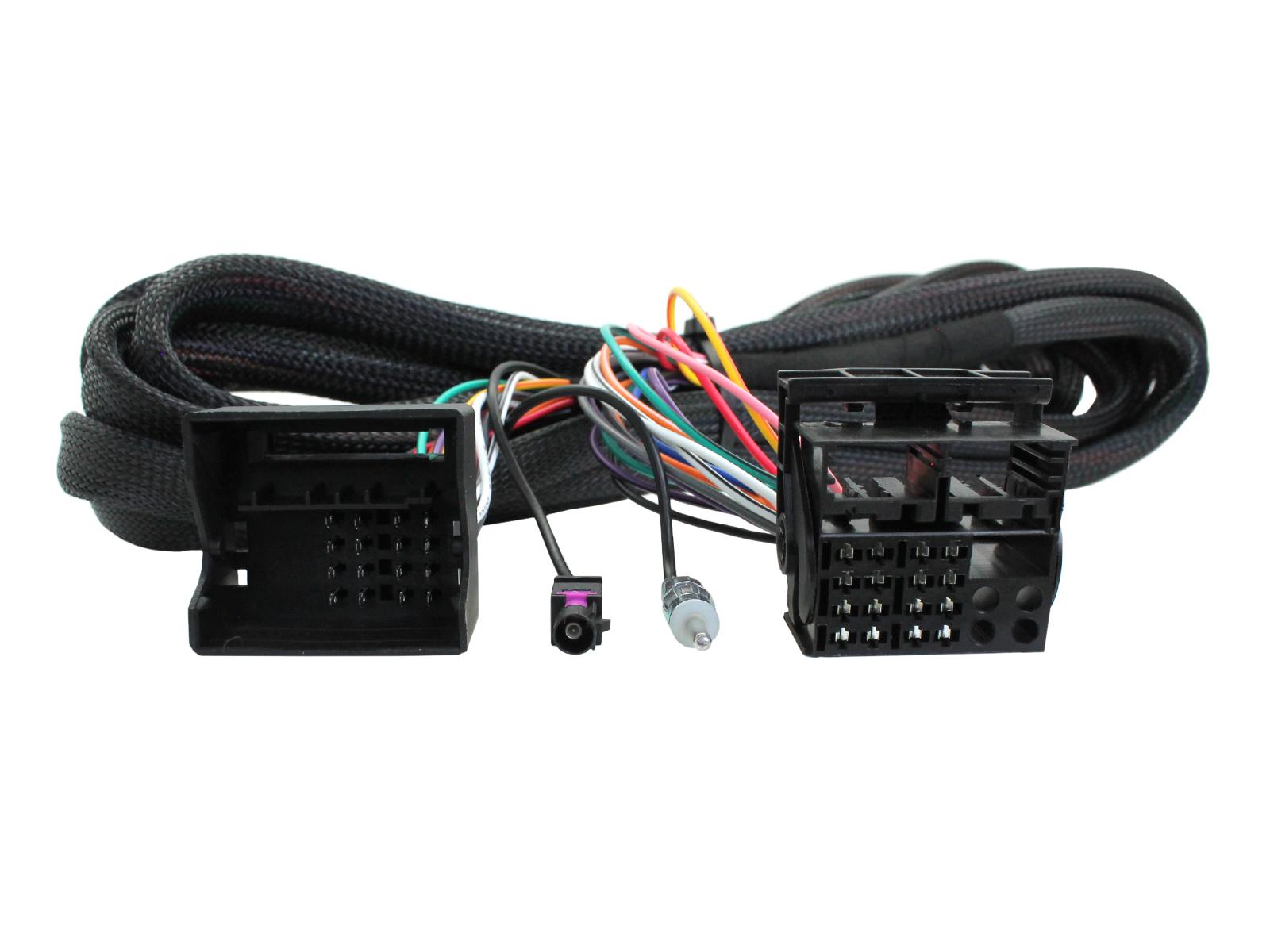
The Professional Radio wiring harness for the 2008 BMW 328xi isn't just one bundle of wires; it's a carefully organized system. Here are some key components and specifications:
- Power Supply: The radio needs a constant 12V power supply (usually a red or red/white wire) to retain memory settings and provide standby power. It also requires a switched 12V power supply (often a white/red or purple/white wire) that turns on the radio when the ignition is on.
- Ground: A solid ground connection (usually a brown or black wire) is essential for proper operation. Poor grounding can lead to noise and distortion.
- Speaker Outputs: These are the wires that connect the radio to the speakers. Each speaker (front left, front right, rear left, rear right) has a positive and negative wire. These are typically color-coded in pairs (e.g., blue/red and blue/brown).
- CAN Bus Connection: The CAN (Controller Area Network) bus is a communication network that allows different electronic control units (ECUs) in the car to communicate with each other. The radio uses the CAN bus to receive information like vehicle speed, steering wheel controls, and other data. Usually two wires twisted together.
- Antenna Connection: This is the coaxial cable that connects the radio to the antenna, allowing it to receive radio signals.
- MOST Bus Connection (Optional): Some BMWs, especially with more advanced audio systems or navigation, use the MOST (Media Oriented Systems Transport) bus. This is a fiber optic network for high-speed data transfer. Professional Radio usually has it, especially if equipped with navigation system.
- Auxiliary Input (If Equipped): If your radio has an auxiliary input, there will be corresponding wires for the left and right audio channels, as well as a ground.
Symbols and Conventions in the Wiring Diagram
Understanding the symbols used in the wiring diagram is critical to interpreting it correctly. Here's a breakdown of common elements:
- Lines: Solid lines represent wires. Dashed lines may represent shielded cables or connections within a component.
- Colors: Each wire is color-coded, and the diagram will have a color legend. Common colors include red (power), brown (ground), and various combinations for signal wires. For instance, "SW/GE" means "Black/Yellow."
- Connectors: Connectors are represented by symbols that indicate the number of pins and their arrangement. Familiarize yourself with these symbols to identify the correct connector.
- Component Symbols: The diagram will use standardized symbols to represent components like resistors, capacitors, diodes, and integrated circuits. While you don't need to be an electronics expert, recognizing basic components can help you understand the circuit.
- Ground Symbols: There are different ground symbols: chassis ground, signal ground, and earth ground. Make sure you understand which type of ground is being referenced.
How the System Works: Signal Flow and Interconnections
The Professional Radio system in the 2008 BMW 328xi isn't just a standalone unit. It's integrated into the car's overall electronic architecture. When you turn on the ignition, the radio receives power and communicates with other ECUs via the CAN bus. This communication allows the radio to display information like vehicle speed, outside temperature, and diagnostic messages. The CAN bus is essential for features like the factory anti-theft system, which often relies on communication between the radio and the car's immobilizer.
Audio signals from the radio are amplified internally and sent to the speakers via the speaker output wires. If your car is equipped with a separate amplifier (common in higher-end audio systems), the radio may output a low-level signal to the amplifier, which then amplifies the signal and sends it to the speakers. Understanding the flow of the audio signal is crucial for troubleshooting audio problems.
The antenna receives radio signals, which are then processed by the radio's tuner. The radio then decodes the audio signal and outputs it through the speaker outputs. The Professional Radio also often incorporates a CD player and sometimes an auxiliary input, each with its own signal path.
Real-World Use: Basic Troubleshooting Tips
Okay, so you've got the diagram. Now what? Here are a few common troubleshooting scenarios and how the diagram can help:
- No Power to the Radio: Use the diagram to trace the power and ground wires. Check the fuses in the fuse box. Use a multimeter to verify that you have 12V at the radio's power input. If the power is present but the radio still doesn't turn on, the radio itself may be faulty.
- No Sound from One or More Speakers: Use the diagram to identify the speaker output wires for the affected speaker. Check the speaker wiring for damage or loose connections. Use a multimeter to check the speaker's impedance (resistance). If the impedance is very low (near zero) or very high (infinite), the speaker may be blown.
- Distortion or Noise: Check the ground connection. A poor ground can introduce noise into the audio signal. Also, check the speaker wires for shorts to ground or to each other.
- Steering Wheel Controls Not Working: This usually indicates a problem with the CAN bus connection. Check the CAN bus wires for damage or loose connections. Verify that the radio is properly communicating with the car's CAN bus network.
Safety Considerations
Working with automotive electrical systems can be dangerous. Here are some crucial safety precautions:
- Disconnect the Battery: Always disconnect the negative terminal of the battery before working on any electrical system in the car. This prevents accidental shorts and potential electrical shock.
- Avoid Working with Live Wires: Never cut or splice wires with the ignition on. This can damage the car's electronics.
- Use a Multimeter Safely: When using a multimeter, make sure it's set to the correct range and function. Always test the meter on a known voltage source before using it to measure voltage in the car.
- Airbags: Be extremely careful when working near airbags. Accidental deployment can cause serious injury. If you're not comfortable working around airbags, consult a professional.
- Fuel System: The Professional Radio may be close to the fuel pump electrical connection, which poses a fire hazard. Always be extremely careful, disconnect the battery and work in a well-ventilated space.
Remember that incorrect wiring can damage the ECUs.
By thoroughly understanding the Professional Radio wiring harness, you'll be well-equipped to tackle a wide range of audio-related projects and troubleshooting scenarios on your 2008 BMW 328xi. This information is a key resource to avoid electrical system damage and achieve a higher understanding of your vehicle's functions.
I have the complete, high-resolution wiring diagram for the 2008 BMW 328xi Professional Radio that we've been discussing. Contact me, and I can arrange to get you a copy. Armed with this information, you'll be able to approach any audio-related project with confidence.