2008 Chevy Silverado Radio Wiring Harness Adapter
Alright, let's dive into the 2008 Chevy Silverado radio wiring harness adapter. Understanding this system is crucial whether you're upgrading your head unit, troubleshooting audio issues, or simply expanding your knowledge of your truck's electrical system. This article will break down the harness adapter, explain its function, interpret the wiring diagram, and offer some practical troubleshooting tips. We'll assume you have some basic experience working with automotive electrical systems, but we'll define the technical terms along the way.
Purpose of the Radio Wiring Harness Adapter
The primary purpose of a radio wiring harness adapter is to provide a standardized and safe interface between your aftermarket radio (or any other electronic device) and your vehicle's factory wiring. Think of it as a translator between two different languages. Without it, you'd have to cut and splice into the factory wiring harness, which can lead to several problems:
- Damage to the OEM wiring: Cutting wires can damage the factory harness, making it difficult to revert to the original setup or causing future electrical issues.
- Voiding warranties: Tampering with the factory wiring can void your vehicle's warranty, especially if it's related to electrical systems.
- Incorrect wiring: Connecting the wrong wires can damage your new radio, your vehicle's electrical system, or both.
- Increased difficulty of future upgrades: A hacked-up wiring harness makes future modifications or repairs a nightmare.
The harness adapter avoids these problems by providing a plug-and-play connection. One end of the adapter plugs directly into the factory radio connector in your Silverado, while the other end has standardized wire leads that you can easily connect to your aftermarket radio's wiring. This allows for a clean, reversible, and safe installation.
Key Specs and Main Parts
The 2008 Chevy Silverado radio wiring harness adapter typically consists of two main parts:
- Vehicle-Specific Connector: This is the end that plugs into the factory radio wiring harness in your Silverado. The number of pins and the pinout (the arrangement of the wires) will vary depending on the specific trim level and factory options (e.g., Bose sound system, OnStar). Understanding the pinout is crucial for proper installation.
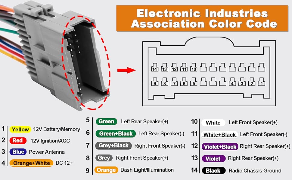
- Standardized Wiring Leads: This is the end that connects to your aftermarket radio. These leads are typically color-coded and labeled with their function (e.g., +12V constant, +12V switched, ground, speaker outputs). The standard wiring colors are determined by the Electronic Industries Alliance (EIA) and are widely used across the automotive industry.
Common wire functions and corresponding colors (though always double-check your specific adapter's documentation) include:
- +12V Constant (Yellow): Provides constant power to the radio, even when the ignition is off. This is often used for memory functions.
- +12V Switched (Red): Provides power to the radio when the ignition is turned on.
- Ground (Black): Provides a return path for the electrical current.
- Speaker Outputs (Various Colors): Each speaker (front left, front right, rear left, rear right) has two wires: a positive (+) and a negative (-) lead. These are often twisted pairs of wires.
- Remote Turn-On (Blue): This wire signals an external amplifier to turn on when the radio is powered on.
- Illumination (Orange/White or similar): Dim the radio display when the headlights are turned on.
Understanding Wiring Diagram Symbols
A wiring diagram is essentially a roadmap of the electrical system. To interpret it effectively, you need to understand the symbols used. Here are some common symbols you'll encounter:
- Solid Lines: Represent wires. The thickness of the line may indicate the wire gauge (size).
- Dotted Lines: Often represent shielded cables or connections that are not directly wired, such as data signals or communication buses (e.g., CAN bus).
- Circles: Can represent connections, splices, or grounding points.
- Rectangles: Often represent components like the radio, amplifier, or other control modules.
- Resistors (Zig-zag lines): Represent resistors, which limit the flow of current.
- Capacitors (Parallel lines): Represent capacitors, which store electrical energy.
- Diodes (Triangle with a line): Allow current to flow in only one direction.
- Ground Symbol (Downward pointing triangle or stacked horizontal lines): Indicates a connection to ground (the vehicle's chassis).
- Numbers and Letters: Labels that identify wires, components, and connectors.
Color codes are also crucial. As mentioned earlier, wire colors are typically standardized, but it's always best to refer to the specific wiring diagram for your adapter and vehicle. The diagram will show which color corresponds to which function.
How It Works
The radio wiring harness adapter bridges the gap between your Silverado's factory wiring and your new radio. Here's how it works:
- The vehicle-specific connector plugs into the factory radio connector. This connector has pins that correspond to the various functions of the factory radio (power, ground, speakers, etc.).
- Inside the adapter, each pin is connected to a wire lead. These wire leads are color-coded and labeled with their function.
- You then connect these wire leads to the corresponding wires on your new radio's wiring harness. For example, you would connect the yellow wire (+12V constant) from the adapter to the yellow wire (+12V constant) on the radio.
By using the adapter, you're essentially creating a one-to-one mapping between the factory wiring and your new radio without cutting or splicing any wires. This makes the installation process much easier and safer.
Real-World Use: Basic Troubleshooting Tips
Even with a harness adapter, things can sometimes go wrong. Here are some basic troubleshooting tips:
- No Power: Double-check the +12V constant (yellow) and +12V switched (red) connections. Use a multimeter to verify that you're getting voltage on these wires when the ignition is on (for the switched wire) and off (for the constant wire). Also, make sure the ground (black) wire is properly grounded.
- No Sound: Check the speaker wire connections. Ensure that the positive (+) and negative (-) wires for each speaker are connected correctly. Verify that the speaker wires are not shorted to ground.
- Radio Resets or Loses Memory: This usually indicates a problem with the +12V constant (yellow) connection. Ensure that this wire is properly connected and receiving a constant voltage.
- Distorted Sound: Check the speaker wiring for shorts or loose connections. Make sure the speaker impedance (measured in ohms) is compatible with your radio's amplifier.
- Fuses Blowing: This indicates a short circuit. Check all wiring connections for damaged insulation or wires that are touching metal.
Safety: Highlighting Risky Components
Working with automotive electrical systems can be dangerous. Here are some safety precautions to keep in mind:
- Disconnect the Battery: Always disconnect the negative terminal of your vehicle's battery before working on any electrical components. This will prevent accidental short circuits and electrical shocks.
- Use a Multimeter: A multimeter is an essential tool for troubleshooting electrical problems. Use it to check for voltage, continuity, and resistance.
- Protect Your Eyes: Wear safety glasses to protect your eyes from sparks or debris.
- Work in a Well-Ventilated Area: When soldering wires, work in a well-ventilated area to avoid inhaling harmful fumes.
- Be Careful with Wiring: Avoid pulling or tugging on wires, as this can damage them or their connections.
- Understand Wire Gauge: Use the correct gauge wire for each connection. Using a wire that is too small can cause it to overheat and potentially start a fire.
- Identify Airbag Wires: Never cut or tamper with airbag wires. These wires are typically bright yellow and are clearly labeled. Mishandling airbag wires can cause the airbags to deploy, which can result in serious injury.
Specifically, when dealing with the radio harness, be extremely careful around the airbag system wiring if it happens to be routed near the radio. A sudden deployment of the airbag during installation could have severe consequences.
By understanding the 2008 Chevy Silverado radio wiring harness adapter, its components, and how it works, you can safely and effectively upgrade your radio or troubleshoot audio problems. Remember to always consult the specific wiring diagram for your adapter and vehicle, and to take the necessary safety precautions. Happy wiring!
We have a comprehensive wiring diagram file available for download that covers the 2008 Chevy Silverado radio wiring harness. This diagram includes detailed pinouts, color codes, and component locations. If you are interested in receiving this file, please contact us through the methods listed at the bottom of this page.