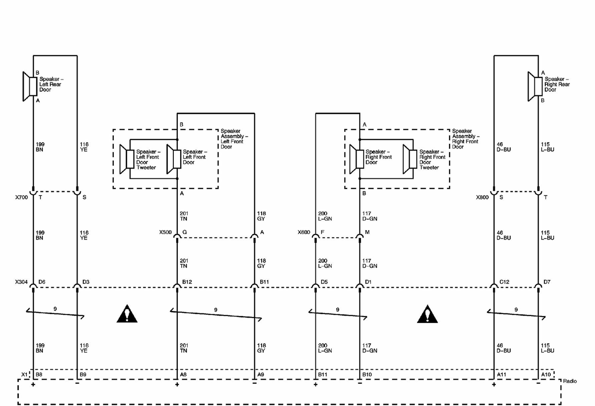
2008 Chevy Trailblazer Radio Wiring Diagram
Understanding the 2008 Chevy Trailblazer radio wiring diagram is crucial for a variety of reasons, whether you're tackling a head unit replacement, installing aftermarket audio equipment, diagnosing electrical problems, or simply trying to better understand your vehicle's audio system. This guide provides a comprehensive overview of the wiring diagram, equipping you with the knowledge to confidently work on your Trailblazer's radio system. We'll walk through the purpose of the diagram, its key components, how it functions, and how to use it for troubleshooting, along with critical safety considerations.
Purpose of the 2008 Chevy Trailblazer Radio Wiring Diagram
The radio wiring diagram serves as a roadmap for your Trailblazer's audio system. It's a visual representation of how all the components – the head unit (radio itself), speakers, amplifier (if equipped), antenna, and wiring harnesses – are interconnected. Without it, working on the radio system becomes a game of guesswork, potentially leading to damaged components, short circuits, or even fire hazards. Specifically, the diagram helps you:
- Identify wires: Pinpointing the correct wires for power, ground, speakers, and communication signals.
- Install aftermarket equipment: Connecting a new head unit, amplifier, or speakers without damaging existing wiring.
- Troubleshoot problems: Diagnosing issues like a blown fuse, a speaker that isn't working, or a radio that won't turn on.
- Repair damaged wiring: Correctly splicing or replacing damaged wires.
- Learn about the system: Gain a deeper understanding of how your vehicle's audio system is designed.
Key Specs and Main Parts
The 2008 Chevy Trailblazer radio system, depending on the trim level, can have varying complexities. The diagram typically covers the following components:
- Head Unit (Radio): The central control unit for the audio system. It receives signals from various sources (AM/FM, CD, AUX) and outputs audio to the speakers. This diagram will show the pinouts and what each pin is responsible for (power, ground, speakers etc.)
- Speakers: The devices that convert electrical signals into audible sound. The Trailblazer has front and rear speakers, and sometimes a center channel speaker.
- Amplifier (Optional): Some Trailblazers come equipped with a factory amplifier to boost the audio signal to the speakers. If present, the diagram will show its location and connections. This amplifier is crucial to identify when installing aftermarket equipment.
- Antenna: The device that receives radio signals.
- Wiring Harnesses: The bundles of wires that connect all the components. These are often color-coded, but the diagram is still essential to confirm the correct wire assignments. Understanding the connector pin-outs is extremely important here.
- Grounding Points: Secure locations on the vehicle's chassis where ground wires are connected. Good grounding is essential for proper audio system operation.
- Fuses: Protective devices that prevent damage from overcurrent. The diagram will usually indicate the location of the radio fuse.
Key Specs: While the diagram doesn't typically provide precise voltage or current ratings, it's important to note that the radio system operates on the vehicle's 12V DC electrical system. Understanding the amperage rating of the radio fuse is critical for safety and preventing electrical fires.
Understanding the Symbols and Conventions
Radio wiring diagrams use standardized symbols and conventions to represent electrical components and connections. Here's a breakdown of common elements:
- Lines: Lines represent wires. Thicker lines may indicate wires carrying higher current.
- Colors: Wires are color-coded to aid in identification. For example, a red wire might indicate a +12V power wire, while a black wire might indicate a ground wire. The diagram key will decode all color conventions.
- Component Symbols: Each component (resistors, capacitors, diodes, etc.) has a specific symbol. For basic radio work, you mainly need to recognize the head unit, speakers, antenna, and amplifier symbols.
- Ground Symbol: This symbol (usually a series of horizontal lines diminishing in size) indicates a connection to the vehicle's chassis ground.
- Connector Symbols: These represent the plugs that connect the wiring harnesses to the various components. The diagram will show the pin arrangement within the connector.
- Numbers/Letters: These indicate wire gauges, circuit numbers, or pin numbers on connectors. This is critical to identifying which wires do what in a connector.
Take your time to study the legend or key associated with the diagram. This key translates symbols and colors used, preventing misinterpretation and potential wiring mistakes. Different manufacturers might use slightly different symbols, so consulting the correct legend is essential.
How It Works: Tracing the Signal Flow
The diagram illustrates the flow of electrical signals through the audio system. Here's a simplified explanation:
- Power Supply: The head unit receives power from the vehicle's battery through a dedicated fuse. This fuse protects the radio from overcurrent.
- Input Signals: The head unit receives input signals from various sources, such as the antenna (for radio signals), a CD player, or an auxiliary input.
- Signal Processing: The head unit processes these signals, amplifies them (if no separate amplifier is present), and sends them to the speakers.
- Speaker Output: The head unit sends separate audio signals to each speaker (front left, front right, rear left, rear right).
- Amplifier (If Equipped): If a separate amplifier is present, the head unit sends a low-level signal to the amplifier, which amplifies the signal and sends it to the speakers.
- Grounding: All components are grounded to the vehicle's chassis to complete the electrical circuit.
Real-World Use: Basic Troubleshooting
The radio wiring diagram is your best friend when troubleshooting audio system problems. Here are some common scenarios and how the diagram can help:
- Radio Doesn't Turn On: Check the radio fuse using the diagram to locate it. If the fuse is blown, replace it. If the fuse continues to blow, there's a short circuit somewhere in the wiring. Use the diagram to trace the power wire and look for damaged insulation or loose connections.
- Speaker Not Working: Use the diagram to identify the speaker wire from the head unit or amplifier to the affected speaker. Use a multimeter to check for continuity in the wire. If the wire is good, the speaker itself may be faulty.
- Distorted Sound: This can be caused by a loose speaker connection or a problem with the head unit or amplifier. Use the diagram to check the speaker connections and test the head unit and amplifier outputs.
- Installing a New Head Unit: The diagram is essential for identifying the correct wires for power, ground, speakers, and remote turn-on (for an amplifier). Match the wires from the new head unit to the corresponding wires in the Trailblazer's wiring harness.
Safety Considerations
Working with automotive electrical systems can be dangerous. Here are some crucial safety precautions:
- Disconnect the Battery: Always disconnect the negative battery terminal before working on the electrical system. This prevents accidental short circuits and electrical shocks.
- Use a Multimeter: A multimeter is an essential tool for testing voltage, continuity, and resistance. Learn how to use it properly before working on the electrical system.
- Work in a Well-Lit Area: Good lighting is essential for seeing what you're doing and avoiding mistakes.
- Avoid Working on Live Wires: Never work on live wires. Always disconnect the battery first.
- Be Careful with Fuses: Never replace a fuse with a higher amperage rating. This can overload the circuit and cause a fire.
- Airbags: Be especially careful when working around the airbags. Refer to the vehicle's service manual for instructions on disabling the airbag system before working in the vicinity. Accidental deployment can cause serious injury.
- Capacitors in Amplifiers: Amplifiers can hold a charge even after the power is disconnected. Be extremely careful when working with amplifiers and discharge any capacitors before touching them. These components can carry a significant voltage and cause a dangerous electrical shock.
By understanding the 2008 Chevy Trailblazer radio wiring diagram and following these safety precautions, you can confidently work on your vehicle's audio system and enjoy enhanced sound quality and functionality. Remember to double-check all your connections and consult the diagram whenever you're unsure about something. When in doubt, it's always best to consult with a qualified automotive electrician.
We have a copy of the 2008 Chevy Trailblazer Radio Wiring Diagram available for download. This will allow you to zoom in on specific sections and get a closer look at the wire colors and pin locations.