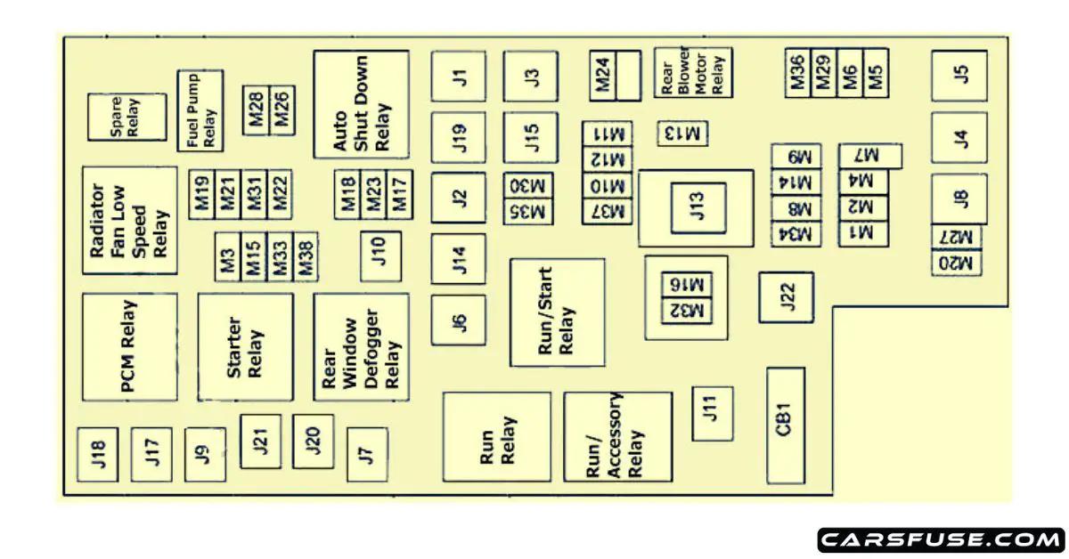
2008 Chrysler Town And Country Fuse Box Diagram
The 2008 Chrysler Town and Country, like any modern vehicle, relies heavily on a complex electrical system. Protecting that system are numerous fuses and relays, strategically housed within fuse boxes. Understanding the 2008 Chrysler Town and Country fuse box diagram is crucial for anyone performing electrical repairs, adding aftermarket accessories, or simply diagnosing common electrical issues. This guide provides a comprehensive overview of the fuse box diagram, its components, and its practical application.
Purpose of the Fuse Box Diagram
The fuse box diagram is essentially a map of your vehicle's electrical protection system. Its primary purpose is to:
- Identify specific fuses and relays: Each component protects a specific circuit or system within the vehicle. The diagram tells you exactly which fuse corresponds to which system (e.g., headlights, power windows, fuel pump).
- Facilitate troubleshooting: When an electrical component malfunctions, checking the corresponding fuse is often the first step in the diagnostic process. The diagram allows you to quickly locate and inspect the relevant fuse.
- Assist with modifications and upgrades: If you're adding aftermarket accessories (e.g., a new sound system, auxiliary lighting), the diagram helps you identify suitable power sources and properly protect the new circuit.
- Provide a quick reference guide: The diagram acts as a readily available reference for electrical component locations, aiding in faster repairs.
Key Specs and Main Parts of the Fuse Box System
The 2008 Chrysler Town and Country typically has two main fuse box locations:
- Interior Fuse Box (Integrated Power Module - IPM): Located under the dashboard, usually on the driver's side. This box primarily houses fuses and relays for interior components like the radio, power windows, lights, and climate control system. The IPM is often a black box, which houses the fuses and relays.
- Under-Hood Fuse Box (Power Distribution Center - PDC): Located in the engine compartment, this box houses fuses and relays for engine management systems, exterior lighting, and other high-current components like the starter motor and ABS (Anti-lock Braking System). The PDC is similar to the IPM but is specifically designed for the components under the hood.
Main Parts:
- Fuses: These are safety devices designed to protect electrical circuits from overcurrent. They consist of a thin strip of metal that melts and breaks the circuit if the current exceeds a predetermined level. Fuses are rated in amperes (amps), which indicates the maximum current they can handle before blowing. Common fuse types include blade fuses (ATO/ATC), mini-blade fuses, and cartridge fuses.
- Relays: These are electromagnetic switches that control high-current circuits using a low-current control signal. They're used to switch on components like headlights, the starter motor, and the fuel pump. A relay consists of a coil, a set of contacts (normally open or normally closed), and an armature.
- Fuse Box Housing: This is the physical enclosure that houses the fuses and relays. It's typically made of plastic and provides protection from the environment.
- Connectors and Wiring: These provide the electrical connections between the fuses, relays, and the vehicle's electrical system.
Understanding Fuse Box Diagram Symbols
Fuse box diagrams use a variety of symbols to represent different components and circuits. Common symbols include:
- Lines: Represent electrical wires or conductors. Thicker lines often indicate heavier gauge wires that carry more current.
- Boxes: Represent fuses or relays. The diagram will often include a number inside the box corresponding to the fuse or relay number.
- Circles: Can represent various components, depending on the diagram. Check the legend for specific meanings.
- Numbers: Indicate the fuse or relay number and its amperage rating (for fuses).
- Abbreviations: Common abbreviations include "IGN" (ignition), "BAT" (battery), "GND" (ground), and "ACC" (accessory).
- Colors: Wire colors are often indicated on the diagram, using abbreviations like "BLU" (blue), "RED" (red), "GRN" (green), "BLK" (black), and "WHT" (white). Understanding the wire color codes can be useful for tracing circuits.
The diagram will also include a legend that defines the meaning of each symbol and abbreviation used. Always refer to the legend to ensure you're interpreting the diagram correctly.
How the Fuse Box System Works
The fuse box system works on the principle of overcurrent protection. When an electrical component draws excessive current (e.g., due to a short circuit or malfunction), the fuse protecting that circuit blows, interrupting the flow of current and preventing damage to the component and the wiring. Relays, on the other hand, act as remotely controlled switches. A low-current signal from a control module (e.g., the ECM - Engine Control Module) energizes the relay's coil, which closes the relay's contacts and allows a high-current circuit to be activated. For instance, when you turn on the headlights, the headlight switch sends a low-current signal to the headlight relay, which then closes the circuit and allows the headlights to draw power directly from the battery through the appropriate fuse.
Real-World Use: Basic Troubleshooting Tips
Here are some basic troubleshooting tips using the fuse box diagram:
- Identify the Symptoms: Determine which electrical component is malfunctioning.
- Consult the Diagram: Use the fuse box diagram to locate the fuse or relay associated with the malfunctioning component.
- Inspect the Fuse: Visually inspect the fuse. If the filament inside the fuse is broken, the fuse is blown and needs to be replaced. You can also use a multimeter to check for continuity across the fuse. A blown fuse will show no continuity.
- Replace the Fuse: Replace the blown fuse with a new fuse of the same amperage rating. Using a fuse with a higher amperage rating can be dangerous and can damage the electrical system.
- Test the Component: After replacing the fuse, test the component to see if it's working correctly. If the fuse blows again immediately, there's likely a short circuit in the wiring or a problem with the component itself. In this case, further diagnosis is required.
- Check the Relay (If Applicable): If the component is controlled by a relay, you can test the relay by swapping it with a known good relay or by using a multimeter to check for continuity and voltage.
Example: If your radio is not working, consult the interior fuse box diagram to locate the fuse labeled "Radio" or "Audio System". Remove the fuse and visually inspect it. If the fuse is blown, replace it with a new fuse of the correct amperage rating. If the radio still doesn't work, the problem may be with the radio itself or the wiring harness.
Safety Precautions
Working with automotive electrical systems can be dangerous. Here are some important safety precautions:
- Disconnect the Battery: Always disconnect the negative battery terminal before working on any electrical components. This will prevent accidental short circuits and electrical shocks.
- Use Proper Tools: Use insulated tools designed for automotive electrical work.
- Never Bypass Fuses: Never bypass a fuse by using a wire or a piece of metal. This can overload the circuit and cause a fire.
- Replace with Correct Amperage: Always replace a blown fuse with a fuse of the same amperage rating.
- Be Aware of High-Current Components: Be especially careful when working with high-current components like the starter motor and alternator. These components can deliver a dangerous electrical shock. The airbag system is also particularly sensitive, and improper handling can lead to accidental deployment.
- Consult a Professional: If you're not comfortable working on the electrical system, consult a qualified mechanic.
The ABS (Anti-lock Braking System) and airbags are critical safety systems. If you suspect issues with these systems, professional diagnosis is always recommended. Incorrect repairs could compromise their functionality.
By understanding the 2008 Chrysler Town and Country fuse box diagram, you can effectively diagnose and repair common electrical issues, saving time and money. Remember to always prioritize safety and consult a professional if you're unsure about any aspect of the repair process.
We have a detailed, high-resolution PDF file of the 2008 Chrysler Town and Country fuse box diagram available for download. This file includes both the interior and under-hood fuse box diagrams, as well as detailed information on fuse and relay locations. This resource is an invaluable tool for any DIY mechanic or car enthusiast working on this vehicle.