2008 Dodge Ram 1500 Exhaust System Diagram
The 2008 Dodge Ram 1500 is a popular truck, and understanding its exhaust system is crucial for maintenance, repairs, and even performance upgrades. This article provides a detailed explanation of the 2008 Dodge Ram 1500 exhaust system diagram, equipping you with the knowledge to diagnose issues, perform repairs, or plan modifications with confidence. Knowing the components and how they interact empowers you to tackle exhaust-related problems effectively.
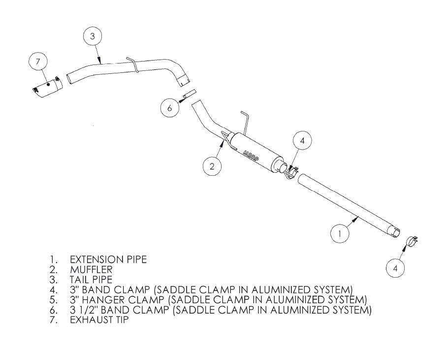
Purpose of the Exhaust System Diagram
An exhaust system diagram serves as a visual roadmap to the entire exhaust setup. It's more than just a pretty picture; it's an invaluable tool for:
- Diagnosis: Identifying the location of leaks, damaged components, or obstructions within the exhaust system.
- Repairs: Understanding the layout and connections of various parts before disassembly and reassembly.
- Modifications: Planning aftermarket exhaust upgrades, such as cat-back systems, headers, or muffler replacements.
- Learning: Gaining a deeper understanding of the exhaust system's function and its role in the overall vehicle operation.
Without a clear diagram, you might be working blindly, potentially causing further damage or wasting time. The diagram provides the necessary visual reference to perform tasks accurately and efficiently.
Key Specs and Main Parts of the 2008 Dodge Ram 1500 Exhaust System
The 2008 Dodge Ram 1500 came with several engine options, each influencing the exhaust system configuration. We'll focus on the general layout, noting potential variations.
Main Components:
- Exhaust Manifolds: These are bolted directly to the engine cylinder heads and collect exhaust gases from each cylinder. They are typically made of cast iron or, in performance applications, stainless steel.
- Catalytic Converters: Located downstream of the manifolds, catalytic converters use catalysts (platinum, palladium, and rhodium) to convert harmful pollutants (hydrocarbons, carbon monoxide, and nitrogen oxides) into less harmful substances. The number of catalytic converters varies depending on the engine and emissions regulations.
- Oxygen Sensors (O2 Sensors): These sensors monitor the oxygen content in the exhaust gases. The upstream sensors (before the catalytic converter) provide feedback to the engine control unit (ECU) to adjust the air-fuel mixture. The downstream sensors (after the catalytic converter) monitor the converter's efficiency.
- Muffler: The muffler reduces exhaust noise by using a series of chambers and baffles to dampen sound waves.
- Resonator (Optional): Some models include a resonator, which further reduces noise and helps to tune the exhaust note.
- Exhaust Pipes: These pipes connect all the components, carrying the exhaust gases from the engine to the atmosphere.
- Tailpipe: The final section of the exhaust system that exits the vehicle, usually located at the rear.
- Hangers and Mounts: Rubber or metal hangers that support the exhaust system and isolate it from the vehicle's chassis, reducing vibration and noise transmission.
- Flanges and Gaskets: These provide sealed connections between the various exhaust components.
Typical Exhaust System Configuration (5.7L Hemi): For the popular 5.7L Hemi engine, the exhaust system typically includes two exhaust manifolds, two catalytic converters (often combined into one unit per bank), two upstream O2 sensors, two downstream O2 sensors, a muffler, and a tailpipe. The system is generally a dual exhaust configuration from the manifolds back to the muffler, then may merge into a single pipe after the muffler.
Symbols and Diagram Conventions
Exhaust system diagrams use specific symbols and conventions to represent components and connections. Understanding these symbols is crucial for interpreting the diagram correctly.
- Lines: Solid lines typically represent exhaust pipes. The thickness of the line may indicate the pipe diameter.
- Dashed Lines: Dashed lines may represent vacuum lines related to emissions control systems, or control wires to sensors.
- Boxes/Rectangles: These usually represent components like catalytic converters or mufflers. The shape and internal markings might indicate the type of component.
- Circles/Ovals: These can represent oxygen sensors or flanges.
- Arrows: Arrows indicate the direction of exhaust gas flow.
- Color Coding: While not always present, color coding might be used to differentiate between different sections of the exhaust system or to highlight specific components. Refer to the diagram's legend for color code explanations if provided.
- Numbering/Lettering: Components are often labeled with numbers or letters that correspond to a key or legend on the diagram. This key provides specific information about each component, such as its part number or function.
Example: A rectangle with internal cross-hatching might represent a catalytic converter, while a small circle with the label "O2S" indicates an oxygen sensor.
How the Exhaust System Works
The exhaust system's primary function is to safely and efficiently remove exhaust gases from the engine, reduce harmful emissions, and minimize noise. The process begins when the exhaust valves open in the engine cylinders, releasing the burnt air-fuel mixture into the exhaust manifolds. The exhaust gases then flow through the catalytic converters, where pollutants are converted into less harmful substances. Next, the gases pass through the muffler and resonator (if equipped) to reduce noise levels. Finally, the exhaust gases exit the vehicle through the tailpipe.
Oxygen sensors play a critical role in maintaining optimal engine performance and emissions control. The upstream sensors provide feedback to the ECU, allowing it to adjust the air-fuel mixture to achieve the ideal stoichiometric ratio (14.7:1 air-fuel ratio). The downstream sensors monitor the catalytic converter's efficiency, alerting the ECU if the converter is not functioning correctly.
Real-World Use: Basic Troubleshooting Tips
The exhaust system diagram can be invaluable for troubleshooting common exhaust-related problems:
- Exhaust Leaks: Use the diagram to locate potential leak points, such as flanges, welds, or damaged pipes. Listen for hissing or popping sounds when the engine is running, and inspect the area visually for signs of soot or corrosion.
- Catalytic Converter Failure: A malfunctioning catalytic converter can cause a check engine light and reduced engine performance. The diagram helps you locate the converters and the associated O2 sensors, which are essential for diagnosing converter issues.
- Muffler Damage: Use the diagram to identify the muffler's location and inspect it for rust, dents, or holes. A damaged muffler can result in excessive noise.
- O2 Sensor Problems: The diagram shows the location of the O2 sensors, allowing you to access them for testing or replacement. Faulty O2 sensors can cause poor fuel economy and engine performance.
Troubleshooting Example: If you suspect an exhaust leak, start by visually inspecting the flanges and welds along the exhaust pipes, referring to the diagram to pinpoint the exact locations. You can also use a soapy water solution to spray on suspected leak areas; bubbles will form where there's a leak.
Safety Precautions
Working on the exhaust system involves several safety hazards:
- Hot Exhaust Components: The exhaust system can reach extremely high temperatures. Allow the engine and exhaust system to cool completely before working on them.
- Exhaust Gases: Exhaust gases contain harmful pollutants, including carbon monoxide. Work in a well-ventilated area.
- Sharp Edges: Exhaust pipes and components can have sharp edges. Wear gloves to protect your hands.
- Lifting the Vehicle: If you need to lift the vehicle to access the exhaust system, use jack stands to support the vehicle securely. Never work under a vehicle supported only by a jack.
- Eye Protection: Wear safety glasses to protect your eyes from debris and rust.
Important: Catalytic converters contain precious metals and are valuable targets for theft. Consider installing security measures to protect your catalytic converter.
Armed with this knowledge and a reliable diagram, you're well-equipped to tackle many common exhaust system issues on your 2008 Dodge Ram 1500. Remember to prioritize safety and consult a qualified mechanic if you're unsure about any aspect of the repair process.
We have a high-resolution PDF version of the 2008 Dodge Ram 1500 exhaust system diagram available for download. This diagram will provide even greater detail and clarity for your repairs and modifications.