2008 Ford Edge Stereo Wiring Diagram
The 2008 Ford Edge stereo wiring diagram is your roadmap to understanding, modifying, or repairing the audio system in your vehicle. Whether you're upgrading your head unit, installing aftermarket speakers, diagnosing a speaker issue, or just trying to understand how all the audio components interact, this diagram is an invaluable resource. It allows you to trace circuits, identify wire functions, and safely work on your car's audio system without causing damage or electrical shorts. We have a copy of the full diagram available for download, linked at the end of this article.
Key Specs and Main Parts of the 2008 Ford Edge Audio System
Before diving into the intricacies of the wiring diagram, let's establish some fundamental specifications and identify the main components involved in the 2008 Ford Edge audio system. These include:
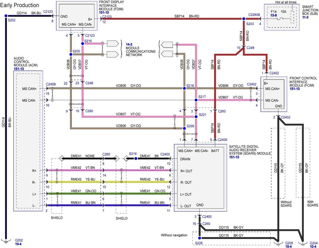
- Head Unit: The brains of the operation. This is where you select your audio source (radio, CD, AUX), control volume, and often manage other vehicle functions (depending on the trim level and factory options). The head unit for the 2008 Edge can vary depending on the factory installed options. Some had a basic AM/FM/CD player while others included navigation or a touch screen interface.
- Speakers: The transducers that convert electrical signals into audible sound. The 2008 Edge typically has speakers in the front doors, rear doors (or rear deck in some models), and sometimes tweeters in the A-pillars or dashboard.
- Amplifier (if equipped): Some higher trim levels of the 2008 Edge came with a factory amplifier. This component boosts the low-level audio signal from the head unit to a level suitable for driving the speakers. Identifying if you have a factory amplifier is crucial before changing out any factory components.
- Wiring Harnesses: Bundles of wires that connect all the components together. These harnesses contain numerous individual wires, each with a specific function. They provide power, ground, audio signals, and control signals throughout the system.
- Connectors: The physical interfaces that plug the wiring harnesses into the various components. Different connectors have different pin configurations, so it's essential to identify the correct connector for each component.
Understanding the Wiring Diagram Symbols
A wiring diagram is a symbolic representation of the electrical circuit. Understanding these symbols is paramount for accurate interpretation. Let's break down some of the common symbols you'll encounter:
- Lines: Solid lines represent wires. Thicker lines may indicate power or ground wires carrying higher current. Dashed lines can represent shielded cables or connections to optional features.
- Colors: Each wire is color-coded, and the diagram provides a key (typically at the bottom or side) that deciphers these color codes. For example, "RD" might represent a red wire, "BK" a black wire (usually ground), "WH" a white wire, etc. Knowing the wire colors is *critical* for identifying the correct wires when working in the vehicle.
- Component Symbols: Each component (e.g., head unit, speaker, amplifier) is represented by a specific symbol. These symbols are often simplified representations of the actual components. A speaker might be represented by a circle with a cross, while a resistor might be a zigzag line.
- Ground Symbols: Ground connections are typically represented by an inverted triangle or a series of horizontal lines that become shorter as they descend. Grounding is crucial for completing the electrical circuit.
- Connector Symbols: Connectors are shown as rectangles or circles with numbered or lettered pins. These indicate the order and position of the wires within the connector.
- Fuses and Relays: Fuses are depicted as a line with a small squiggle through it, indicating its overcurrent protection. Relays are shown as a coil and a set of contacts, illustrating how they switch circuits.
Important Note: Ford wiring diagrams often use abbreviations for wire colors (e.g., LB for Light Blue, GY for Gray, GN for Green). Always refer to the color code key on the diagram itself for accurate identification.
How the 2008 Ford Edge Audio System Works
The basic operation is as follows:
- Power Supply: The audio system receives power from the vehicle's battery. A fuse protects the system from overcurrent. The ignition switch also provides a signal to the head unit to turn it on/off.
- Signal Generation: The head unit generates the audio signal. This can come from the radio tuner, CD player, or an external source (AUX input).
- Signal Processing: The head unit might apply basic equalization or tone controls to the audio signal. If the vehicle is equipped with a factory amplifier, the head unit sends a low-level signal to the amplifier.
- Amplification: The amplifier (if present) boosts the low-level audio signal to a higher power level.
- Speaker Output: The amplified audio signal is sent to the speakers, which convert the electrical signal into sound waves.
- Ground Return: Each component requires a ground connection to complete the electrical circuit. The ground wires are typically connected to the vehicle's chassis.
Real-World Use: Basic Troubleshooting Tips
The wiring diagram is especially helpful when diagnosing audio system problems. Here are a few examples:
- No Sound from One Speaker: Use the wiring diagram to trace the speaker wires back to the head unit or amplifier. Check for loose connections, damaged wires, or a blown speaker. Use a multimeter to test the continuity of the wires.
- Head Unit Not Turning On: Check the power and ground connections to the head unit. Use the wiring diagram to identify the correct power wires and ground wires. Check the fuse for the audio system.
- Static or Distortion: Check the speaker wires for shorts or damage. A short circuit can cause static or distortion. Verify proper grounding throughout the system.
- Upgrading Speakers: Use the wiring diagram to identify the speaker wires and polarity. This ensures that you connect the new speakers correctly. Pay close attention to the impedance of the speakers (typically 4 ohms) to avoid damaging the head unit or amplifier.
When troubleshooting, always start with the simplest checks first (e.g., fuses, connections) before moving on to more complex diagnostics.
Safety Precautions
Working with electrical systems in a vehicle can be hazardous. Here are some essential safety precautions:
- Disconnect the Battery: Before working on any electrical components, always disconnect the negative terminal of the battery. This prevents accidental shorts and electrical shocks.
- Use Proper Tools: Use insulated tools designed for automotive electrical work. This includes wire strippers, crimpers, multimeters, and test lights.
- Avoid Water: Never work on electrical systems in wet conditions.
- Identify Airbag Wiring: Be extremely careful when working near airbag wiring. Accidental activation of an airbag can cause serious injury. If you are unsure about how to proceed, consult a qualified technician.
- Understand Component Voltage: Be aware that some components, such as capacitors in the amplifier, can store a charge even after the battery is disconnected. Discharge these components carefully before handling them.
- Special Note About Amplifiers: Factory and aftermarket amplifiers often have large capacitors that hold a dangerous electrical charge even with the battery disconnected. Discharge these capacitors properly before handling the amplifier.
Incorrect wiring can damage the audio system or even cause a fire. Always double-check your work and consult the wiring diagram frequently.
The 2008 Ford Edge stereo wiring diagram is a valuable tool for anyone working on the audio system. By understanding the symbols, components, and wiring configurations, you can diagnose problems, perform upgrades, and ensure the safe and reliable operation of your car's audio system. We have the full diagram available for download: [Link to Download Diagram].