2008 Ford Escape Radio Wiring Diagram
The 2008 Ford Escape radio wiring diagram is an invaluable resource for any intermediate car owner, modder, or DIY mechanic looking to understand, troubleshoot, or upgrade their vehicle's audio system. This detailed guide will break down the intricacies of the wiring diagram, empowering you to confidently tackle radio-related projects on your Escape.
Purpose of Understanding the 2008 Ford Escape Radio Wiring Diagram
Why bother with a wiring diagram? Several reasons. Firstly, it's essential for repairs. If your radio suddenly stops working, or individual speakers cut out, the diagram helps you trace the problem back to its source, be it a faulty wire, a loose connection, or a failing component. Secondly, for upgrades, like installing a new head unit, adding an amplifier, or integrating aftermarket speakers, the diagram provides the necessary information to connect everything correctly, preventing potential damage to your vehicle's electrical system. Finally, and perhaps most importantly, it provides a deeper understanding of how your vehicle's audio system is integrated with the rest of the car's electronics. Understanding the wiring provides a good basis for safely working on other components as well. This knowledge is power, allowing you to diagnose and solve problems yourself, saving you time and money.
Key Specs and Main Parts of the Audio System
Before diving into the diagram itself, let's briefly outline the key components of the 2008 Ford Escape audio system:
- Head Unit: The brain of the system, responsible for playing audio from various sources (radio, CD, AUX, etc.), controlling volume, and often integrating with other vehicle functions.
- Speakers: Convert electrical signals into audible sound. The 2008 Escape typically features speakers in the front doors and rear of the cabin. The number of speakers and their specific placement may vary depending on the trim level.
- Antenna: Receives radio signals. Usually located on the roof or integrated into a window.
- Wiring Harness: A bundle of wires that connect all the audio components. This is what the diagram focuses on.
- Connectors: Plugs that attach the wiring harness to the head unit, speakers, and other components.
- Ground Connections: Crucial for completing the electrical circuits. Poor ground connections are a common source of audio problems.
- Amplifier (Optional): Some Escapes came equipped with a factory amplifier, usually located under a seat or in the trunk area. This amplifies the signal from the head unit before sending it to the speakers.
Decoding the Symbols: Wires, Colors, and Icons
A wiring diagram uses standardized symbols and conventions to represent electrical components and connections. Understanding these symbols is crucial for interpreting the diagram accurately.
- Lines: Represent wires. Thicker lines may indicate wires carrying higher current.
- Colors: Each wire is assigned a specific color, indicated by abbreviations (e.g., WH for White, BK for Black, RD for Red, GN for Green, BU for Blue, YE for Yellow). A wire might be labeled "WH/BK," meaning a white wire with a black stripe. These color codes are crucial for identifying the correct wires during troubleshooting or installation.
- Circles or Dots: Indicate wire connections or splices. A filled-in circle signifies a direct connection, while an open circle may indicate a splice or terminal.
- Rectangles: Often represent components like the head unit, speakers, or amplifier.
- Ground Symbol: Typically a series of descending lines or a triangle, indicating a connection to the vehicle's chassis ground.
- Fuses: Represented by a wavy line inside a rectangle, these are critical safety devices that protect the electrical system from overcurrent.
- Connectors: Indicated with symbols that generally suggest the physical shape of the connector. Often, the connector will have a number indicating which connector you're looking at in the car, such as C290a, C290b, etc.
Understanding wire colors is key. Ford uses a standardized color code. Common colors include:
- BK: Black
- BN: Brown
- BU: Blue
- GN: Green
- GY: Gray
- LB: Light Blue
- LG: Light Green
- OG: Orange
- PK: Pink
- RD: Red
- TN: Tan
- VT: Violet
- WH: White
- YE: Yellow
How It Works: Tracing the Signal Path
The 2008 Ford Escape radio wiring diagram depicts the flow of electrical signals within the audio system. Power from the battery is fed to the head unit, often through a fuse. The head unit processes the audio signal and sends it to the speakers (either directly or through an optional amplifier). The diagram shows the specific wires used for each function: power, ground, speaker outputs (front left, front right, rear left, rear right), antenna, and any control signals (e.g., steering wheel controls). By tracing these lines, you can understand how each component interacts with the others.
For example, if you're trying to diagnose why the front left speaker isn't working, you would follow the wiring diagram from the head unit's front left speaker output to the speaker itself, checking for breaks in the wire, loose connections, or a faulty speaker. The diagram will also show if there are any intermediate connectors or splices in the circuit that could be the source of the problem.
Real-World Use: Basic Troubleshooting Tips
Here are a few practical troubleshooting scenarios where the wiring diagram comes in handy:
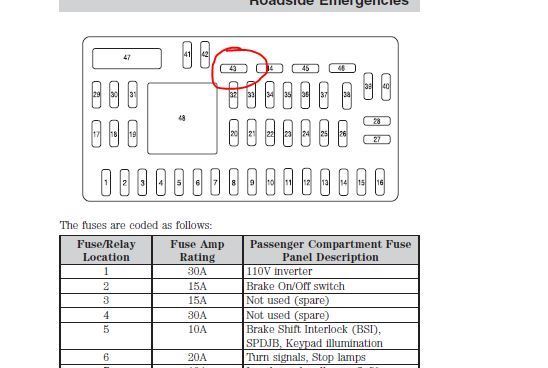
- Radio Not Turning On: Check the power and ground wires connected to the head unit. Use a multimeter to verify that the power wire is receiving 12V and that the ground wire has a good connection to the chassis. Also, check the relevant fuses in the fuse box.
- No Sound From a Speaker: As mentioned earlier, trace the speaker wires from the head unit to the speaker. Check for loose connections or damaged wires. You can also test the speaker itself with a multimeter to see if it's functioning.
- Static or Distortion: This could be caused by a poor ground connection, a loose antenna connection, or interference from other electrical components. Check all ground connections and the antenna cable.
- Aftermarket Head Unit Installation: The wiring diagram is essential for identifying the correct wires for power, ground, speakers, and other functions. Use a wiring harness adapter designed for the 2008 Ford Escape to simplify the installation process and avoid cutting into the factory wiring.
Safety Considerations: Highlighting Risky Components
Working with automotive electrical systems can be dangerous. Always disconnect the negative battery terminal before working on any electrical components to prevent short circuits and electrical shocks. Be especially careful when working with the power wires to the head unit, as these carry a significant amount of current. Never cut or splice wires without properly insulating them afterward. If you're not comfortable working with electrical systems, it's best to consult a qualified technician.
Important: Always consult the diagram before disconnecting or modifying any wiring. Incorrect connections can damage your vehicle's electrical system. Fuses are there to protect the components; if they continue to blow there is an underlying issue that must be addressed. Shorting the fuses by using a higher amperage fuse could be dangerous and cause a fire.
Remember to double-check all connections and wiring before reconnecting the battery. A small mistake can lead to significant problems.
We have a copy of the complete 2008 Ford Escape Radio Wiring Diagram readily available for you to download. This detailed document will be an invaluable asset for any audio-related project you undertake on your Escape.