2008 Ford Escape Stereo Wiring Diagram
Let's dive into the stereo wiring diagram for a 2008 Ford Escape. This document isn't just a pretty picture; it's your roadmap for understanding, repairing, and even upgrading the audio system in your vehicle. Whether you're tackling a blown speaker, installing a new head unit, or just curious about how all those wires connect, this guide will provide a clear path. We'll cover everything from the diagram's purpose and key specs to deciphering the symbols and using it for real-world troubleshooting.
Purpose of the 2008 Ford Escape Stereo Wiring Diagram
The primary purpose of a stereo wiring diagram is to provide a visual and textual representation of the electrical connections within the vehicle's audio system. It serves several crucial roles:
- Repair and Diagnosis: When your audio system malfunctions (no sound, distorted audio, blown fuse, etc.), the wiring diagram helps you trace the circuits to identify the source of the problem. It shows you which wires to check for continuity (a complete electrical path) and voltage.
- Component Replacement: If you need to replace a component like the head unit (radio), speakers, or amplifier, the diagram tells you exactly which wires connect to which terminals. This is essential for avoiding incorrect wiring, which can damage your components or the vehicle's electrical system.
- Aftermarket Installation: Installing aftermarket audio equipment (amplifiers, subwoofers, new speakers, etc.) requires tapping into the existing wiring. The diagram shows you the correct locations to tap into, ensuring proper integration and avoiding conflicts with the factory system.
- Understanding System Architecture: Even if you don't plan on modifying anything, studying the wiring diagram can give you a deeper understanding of how the audio system is designed and how its various components interact.
Key Specs and Main Parts of the 2008 Ford Escape Audio System
Understanding the basic components of the 2008 Ford Escape audio system helps in interpreting the wiring diagram. Here are some key elements to consider:
- Head Unit (Radio): The head unit is the central control point of the audio system. It provides the user interface (buttons, display) for selecting audio sources (radio, CD, auxiliary input, etc.) and controlling volume, tone, and other settings. In the diagram, you'll see connections for power, ground, speakers, antenna, and potentially steering wheel controls.
- Speakers: The 2008 Escape typically features speakers in the front and rear doors. The wiring diagram shows the positive (+) and negative (-) connections for each speaker. Pay close attention to polarity (positive and negative connection). Reversing polarity can cause speakers to be out of phase, resulting in poor sound quality and cancellation of certain frequencies.
- Amplifier (if equipped): Some Escape models came with a factory amplifier, which boosts the audio signal before it reaches the speakers. The wiring diagram will show the input signals from the head unit, the power and ground connections for the amplifier, and the output signals to the speakers. Location of the amp varied, often under the center console or seat.
- Wiring Harnesses: These are bundles of wires that connect the various components of the audio system. The diagram shows the connectors and the individual wires within each harness. Understanding harness locations simplifies tracing wires and identifying connection points.
- Antenna: The antenna receives radio signals. The diagram will show the connection point of the antenna cable to the head unit.
- Grounding Points: Proper grounding is crucial for a stable and noise-free audio system. The diagram will show the locations of the grounding points, where wires are connected to the vehicle's chassis.
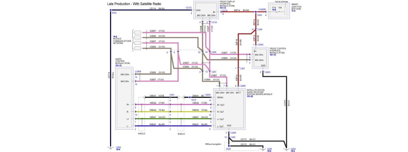
Decoding the Symbols: Lines, Colors, and Icons
A wiring diagram uses a standardized set of symbols to represent electrical components and connections. Here's a breakdown of the most common symbols you'll encounter:
- Lines: Solid lines represent wires. Dashed lines may indicate shielded cables or connections related to specific functions like data communication. The thickness of the line usually doesn't reflect the wire's gauge (thickness), but rather emphasizes the connection's importance in the diagram.
- Colors: Each wire is represented by a specific color code (e.g., Red, Black, White/Green). These colors are standardized within Ford's wiring system. Knowing the color code allows you to identify the correct wire in the vehicle. The diagram will typically include a color key or legend.
- Connectors: Connectors are represented by various shapes, often resembling interlocking rectangles or circles. The diagram will show the pin numbers or letter designations for each wire within the connector. This is vital for correctly connecting aftermarket components or repairing damaged connectors.
- Ground Symbols: A ground symbol typically looks like a series of downward-pointing lines, often resembling an inverted Christmas tree. This indicates a connection to the vehicle's chassis, providing a return path for the electrical current.
- Component Symbols: Components like speakers, resistors, capacitors, diodes, and relays are represented by their standard electronic symbols. While you might not need to understand every symbol, recognizing common components like speakers (a circle with a cone inside) is helpful.
- Fuses: Fuses are critical safety devices. The diagram will indicate the fuse locations and amperage ratings relevant to the audio system.
How It Works: Following the Signal Flow
The wiring diagram essentially shows the path the audio signal takes from the source (head unit) to the speakers. Here's a simplified explanation:
- Power and Ground: The head unit receives power from the vehicle's battery via a fused circuit. It also needs a good ground connection to complete the electrical circuit.
- Signal Generation: The head unit generates the audio signal based on the selected source (radio, CD, etc.).
- Signal Processing: The head unit may include tone controls (bass, treble) and volume controls that adjust the audio signal.
- Amplification (if applicable): If the vehicle has a factory amplifier, the audio signal from the head unit is sent to the amplifier for amplification.
- Speaker Output: The amplified audio signal (or the signal directly from the head unit) is sent to the speakers.
- Sound Production: The speakers convert the electrical signal into sound waves.
Real-World Use: Basic Troubleshooting Tips
Here are some common troubleshooting scenarios and how the wiring diagram can help:
- No Power to Head Unit: Check the fuse identified in the wiring diagram. If the fuse is blown, replace it with a fuse of the same amperage rating. If the fuse blows again, there's likely a short circuit in the wiring. Use the diagram to trace the power wire from the fuse to the head unit, looking for damaged insulation or pinched wires.
- One Speaker Not Working: Use a multimeter to check the speaker wires for continuity. If there's no continuity, the wire may be broken. If there is continuity, test another speaker connected to that wire to isolate problem. Also, check the speaker itself by swapping it with a known working speaker.
- Distorted Sound: Distorted sound can be caused by a blown speaker, a loose connection, or a problem with the head unit or amplifier. Use the wiring diagram to check the speaker connections and the signal path from the head unit to the speaker.
- Static or Noise: Static or noise can be caused by a poor ground connection. Use the wiring diagram to locate the grounding points and ensure they are clean and tight. Also, check for interference from other electrical components in the vehicle.
Safety Considerations
Working with automotive electrical systems can be dangerous. Always follow these safety precautions:
- Disconnect the Battery: Before working on any electrical circuits, disconnect the negative terminal of the vehicle's battery. This will prevent accidental short circuits and electrical shocks.
- Use a Multimeter: A multimeter is an essential tool for troubleshooting electrical problems. Use it to check for voltage, continuity, and resistance.
- Proper Insulation: Ensure that all wires are properly insulated. Use electrical tape or heat shrink tubing to repair damaged insulation.
- Avoid Working with Live Wires: Never work on electrical circuits while the engine is running or the ignition is on.
- Airbags: Be aware of airbag locations. Improper wiring near airbag sensors can cause them to deploy accidentally. Consult a professional if you are unsure about working near airbags.
- Capacitors in Amplifiers: Amplifiers contain large capacitors that can store a significant electrical charge even after the battery is disconnected. Discharge these capacitors before working on the amplifier. This is especially true for aftermarket amplifiers.
We have access to the complete 2008 Ford Escape Stereo Wiring Diagram. You can download it from [insert download location/link here - assume file is available but can't be literally linked in this static text]. This diagram, coupled with the knowledge shared in this article, will be an invaluable resource as you work on your vehicle's audio system.