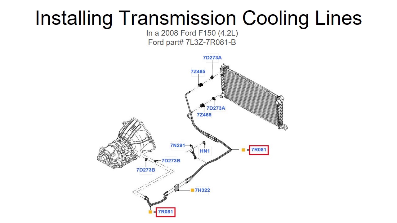
2008 Ford F150 Transmission Cooling Line Diagram
Alright folks, let's dive into the transmission cooling system of the 2008 Ford F-150. Understanding this system is crucial for maintaining the health of your truck's transmission, preventing costly repairs down the line. Whether you're troubleshooting a leak, planning an upgrade, or just want a better grasp of your vehicle's mechanics, a good understanding of the cooling line diagram is invaluable.
Purpose and Importance
The transmission cooling system's primary function is to dissipate heat generated within the transmission. Automatic transmissions rely on hydraulic fluid (ATF) to operate, and this fluid gets incredibly hot during normal operation due to friction from the torque converter, gears, and clutches. Excessive heat is the silent killer of automatic transmissions; it breaks down the ATF, reduces its lubricating properties, and can lead to premature wear and failure of internal components. A properly functioning cooling system ensures the ATF stays within its optimal operating temperature range.
The transmission cooling line diagram serves as a roadmap for this system. It illustrates the routing of the cooling lines, the location of key components, and the direction of fluid flow. This is essential for:
- Troubleshooting leaks: Pinpointing the exact location of a leak is much easier when you know the expected path of the cooling lines.
- Performing repairs: Replacing a damaged line or component requires knowledge of how the system is assembled.
- Planning upgrades: Adding an aftermarket cooler, for example, requires understanding how to integrate it into the existing system.
- General maintenance: Checking the condition of the lines and connections is part of preventative maintenance.
- Learning about your truck: Just expanding your knowledge of how your F-150 works!
Key Specs and Main Parts
The 2008 Ford F-150, depending on the engine and transmission configuration (4R75E or 4R70E), generally utilizes a transmission cooling system that integrates with the radiator. Here are the key components:
- Transmission: The source of the heat and the destination of the cooled ATF. Specifically, the cooling lines connect to ports on the transmission case.
- Transmission Cooling Lines: Typically, rigid metal lines (steel or aluminum) with flexible hose sections at connection points to absorb vibration and allow for movement. These lines transport the hot ATF to the cooler and the cooled ATF back to the transmission.
- Radiator (with Integrated Transmission Cooler): A heat exchanger where the hot ATF is cooled by the engine coolant. Many radiators have a dedicated section for transmission cooling, often a separate chamber within the lower part of the radiator.
- Transmission Cooler (Optional): An external, auxiliary cooler. This is often added for heavy-duty applications like towing to provide additional cooling capacity. It's usually mounted in front of the radiator.
- Hoses and Clamps: Flexible rubber hoses connect the rigid lines to the transmission, radiator, and (if equipped) the external cooler. Clamps secure the hoses to the fittings.
Note: Some F-150 models might have a separate stand-alone transmission cooler, especially those equipped with towing packages. The diagram will clearly show this if applicable.
Symbols and Diagram Interpretation
Understanding the symbols on the cooling line diagram is essential for proper interpretation.
- Solid Lines: Represent the rigid metal cooling lines.
- Dashed Lines: Typically indicate flexible hoses.
- Arrows: Indicate the direction of ATF flow. Pay close attention to these; they tell you which line is the supply and which is the return.
- Component Outlines: The radiator, transmission, and any external coolers will be represented by simplified outlines.
- Fittings and Connections: Small circles or other symbols might indicate fitting types (e.g., quick-connect fittings).
- Color Coding (if present): Some diagrams use color to differentiate between supply and return lines. Red might indicate the hot supply line, while blue might indicate the cooled return line. Always refer to the diagram's legend for color coding information.
Important Note: Ford service manuals often use different line weights to indicate different types of lines. A thicker line might indicate a higher pressure line, for example. The key to understanding the diagram is to always refer to the legend or notes provided with the diagram.
How It Works
The transmission cooling system operates on a simple principle of heat exchange:
- Hot ATF exits the transmission through the supply line.
- The hot ATF flows to the radiator's integrated transmission cooler (or to an external cooler, if equipped).
- Inside the cooler, the hot ATF exchanges heat with the engine coolant (or the ambient air in the case of an external cooler).
- The cooled ATF then returns to the transmission through the return line.
- This cycle repeats continuously as the engine runs, maintaining the ATF within its optimal temperature range.
The transmission oil pump, located inside the transmission, circulates the ATF through the cooling system. The pressure generated by the pump is generally low, but the constant flow is crucial for effective cooling.
Real-World Use and Basic Troubleshooting
Here are some common troubleshooting scenarios where understanding the cooling line diagram is beneficial:
- ATF Leak: Locate the suspected leak. Using the diagram, trace the line back to its origin to identify the component that's leaking (e.g., hose, fitting, cooler).
- Overheating Transmission: Check for obvious signs of damage to the cooling lines or cooler. Ensure the lines are not kinked or blocked. Verify coolant level in the radiator (if using the integrated cooler). Consider adding an external cooler if you frequently tow or haul heavy loads.
- Line Replacement: Use the diagram to determine the correct length and routing of the replacement line. Be sure to use the correct type of hose and fittings.
Common Issues:
- Corroded Lines: Especially in areas with road salt, the metal lines can corrode and leak.
- Leaking Hoses: Hoses can crack, dry rot, or become loose at the connections.
- Clogged Cooler: Debris can accumulate in the cooler, restricting ATF flow.
Safety Considerations
Working on the transmission cooling system involves potential hazards:
- Hot ATF: ATF can be extremely hot. Allow the engine and transmission to cool completely before working on the system. Wear gloves and eye protection.
- Pressure: Although the system operates at relatively low pressure, there might still be residual pressure in the lines. Release the pressure slowly and carefully before disconnecting any lines.
- Flammability: ATF is flammable. Keep sparks and open flames away from the work area.
- Sharp Edges: The metal cooling lines can have sharp edges. Wear gloves to protect your hands.
- Do not work under a vehicle supported only by a jack. Use jack stands.
Specific Risky Components:
- Quick-Connect Fittings: These fittings can be difficult to disconnect and reconnect. Use the correct tool to avoid damaging the fitting.
- Radiator Connections: Be careful when working around the radiator; it can be hot and pressurized.
By carefully following the diagram and taking the necessary precautions, you can safely and effectively troubleshoot and repair your 2008 Ford F-150's transmission cooling system. This knowledge not only saves you money but also empowers you to keep your truck running smoothly for years to come.
We have a downloadable PDF file of the 2008 Ford F-150 Transmission Cooling Line Diagram available for your use. This detailed diagram will provide you with all the information you need to perform repairs, upgrades, and general maintenance on your transmission cooling system.