2008 Gmc Sierra Radio Wiring Diagram
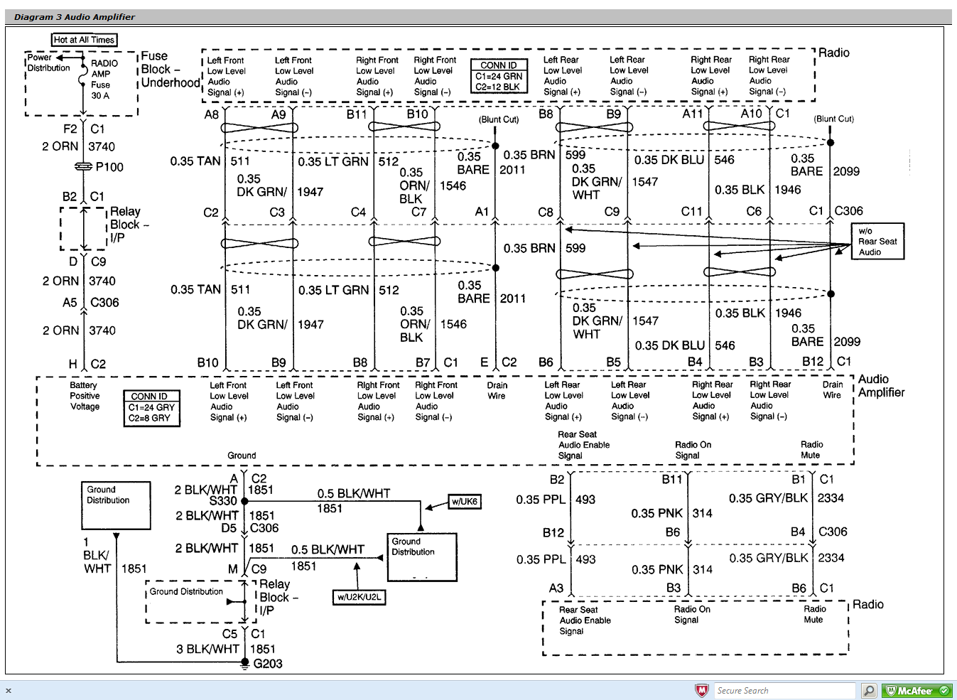
Welcome, fellow gearheads and DIY enthusiasts! Today, we're diving deep into the 2008 GMC Sierra radio wiring diagram. Understanding this schematic is crucial for anyone looking to upgrade their audio system, troubleshoot electrical problems, or simply gain a better understanding of their vehicle's inner workings. We're going to approach this from the perspective of experienced DIYers, so expect a level of detail that empowers you to confidently tackle your own projects. We have the complete wiring diagram available for download, which you can access at the end of this article.
Why This Diagram Matters
The 2008 GMC Sierra, like all modern vehicles, relies heavily on its electrical system, and the radio is a significant part of that. Having access to a reliable wiring diagram can save you time, money, and a whole lot of frustration. Here's why it's so important:
- Audio Upgrades: Planning to install a new head unit, amplifier, or speakers? The wiring diagram is your roadmap to identifying the correct wires for power, ground, speaker connections, and remote turn-on. Avoid cutting the wrong wires and potentially damaging your system!
- Troubleshooting: Radio suddenly stopped working? Speakers cutting out? By using the diagram and a multimeter, you can trace the circuit, identify faults (like shorts, opens, or bad grounds), and pinpoint the problem component.
- Learning Vehicle Electrics: Even if you're not actively working on your radio, studying the wiring diagram provides valuable insights into how automotive electrical systems are designed and interconnected.
- Security System Integration: Installing a new car alarm or remote start system often requires interfacing with the radio's wiring. The diagram shows you which wires to tap into for functions like door triggers or ignition sense.
Key Specs and Main Parts
Before we jump into the diagram itself, let's cover some key specifications and identify the main components typically found in the 2008 GMC Sierra radio system. Keep in mind that specific configurations can vary based on trim level and factory options, but these are the common elements:
- Head Unit (Radio Receiver): This is the brain of the system, responsible for receiving radio signals, playing CDs or MP3s, and controlling audio output. It also often handles integration with features like OnStar and satellite radio.
- Speakers: Typically, you'll find speakers in the front doors, rear doors (if applicable), and sometimes in the dashboard or rear deck.
- Amplifier (if equipped): Higher-end models often include a separate amplifier to boost the audio signal before it reaches the speakers. This provides more power and better sound quality. The amp is often located under one of the front seats.
- Wiring Harnesses: These bundles of wires connect all the components together. The main harness plugs directly into the back of the head unit and contains all the necessary power, ground, speaker, and control wires.
- Antenna: The antenna receives radio signals.
- OnStar Module (if equipped): The OnStar module uses the vehicle's speakers for audio during calls and can also interact with the radio system.
- Bose Amplifier/Speakers (if equipped): If the vehicle has the Bose sound system, there is a Bose amplifier and Bose speakers that are designed for use with the system.
Typical voltage used is 12V DC, which is standard for automotive electrical systems. Power ratings for the speakers will vary, but they're usually in the range of 20-50 watts RMS per channel.
Understanding the Symbols
A wiring diagram is essentially a map of the electrical system, using standardized symbols to represent components and connections. Let's decode some of the most common symbols you'll encounter in the 2008 GMC Sierra radio diagram:
- Lines: Solid lines represent wires. Thicker lines might indicate higher current carrying capacity. Dashed lines often represent shielded wires or ground connections.
- Colors: Each wire is identified by a specific color code (e.g., RED, BLU, GRN, YEL). This makes it much easier to trace wires within the harness. The diagram will have a color code table to help you.
- Circles with Numbers: These represent connection points or terminals within connectors. The numbers correspond to specific pins within the connector.
- Ground Symbol: Usually looks like a series of downward-pointing triangles, indicating a connection to the vehicle's chassis ground.
- Resistor Symbol: A zigzag line representing a resistor, which limits current flow.
- Capacitor Symbol: Two parallel lines, representing a capacitor, which stores electrical energy.
- Diode Symbol: A triangle with a line at the point, representing a diode, which allows current to flow in only one direction.
- Fuses: Identified by a specific symbol and amperage rating. Fuses are crucial for protecting the circuit from overloads. Always replace a blown fuse with one of the same amperage rating. Using a higher amperage fuse can lead to serious damage.
Understanding these symbols is essential to interpreting the diagram accurately. The diagram will include a legend to confirm any symbol. Pay close attention to the wire colors and terminal numbers. These are your primary tools for navigating the system.
How It Works
The 2008 GMC Sierra radio system is a relatively straightforward circuit. Power comes from the vehicle's battery, typically through a fuse in the fuse box. The head unit receives both constant power (for memory functions) and switched power (which turns the unit on and off with the ignition). The head unit processes audio signals from various sources (radio, CD, MP3, etc.) and sends them to the speakers, either directly or through an amplifier.
The wiring diagram illustrates the flow of electricity from the power source, through the components, and back to ground. It shows how each wire is connected and its specific function within the system.
The diagram also highlights any control signals, such as those from the steering wheel controls or the OnStar module. These signals allow the radio to be controlled remotely or integrated with other vehicle systems.
Real-World Use: Basic Troubleshooting Tips
Okay, let's put this knowledge to practical use. Here are a few basic troubleshooting scenarios and how the wiring diagram can help:
- No Power to Radio: Start by checking the fuses related to the radio (usually labeled "Radio" or "Audio"). Use the wiring diagram to identify the power wires going to the head unit. Use a multimeter to check for voltage on these wires. If there's no voltage, the fuse is likely blown, or there's a break in the wiring.
- Speakers Not Working: Use the diagram to identify the speaker wires for the affected speakers. Check the speaker connections at the head unit and at the speakers themselves. If the connections are good, use a multimeter to check for continuity in the speaker wires. If there's no continuity, there's a break in the wire.
- Static or Distortion: This could be caused by a bad ground connection. Use the diagram to identify the ground wires for the radio and amplifier. Ensure that these wires are securely connected to the vehicle's chassis. You may also need to clean the ground connection points.
- Radio Turns On But No Sound: First verify the system isn't muted! If not muted, and you have an aftermarket amplifier, check the remote turn-on wire. Use the diagram to confirm it's receiving 12V when the radio is on. If not, the amp isn't turning on. If the speakers aren't working and you don't have an aftermarket amplifier, the internal amplifier may have failed.
Always disconnect the negative terminal of the battery before working on any electrical component. This will prevent accidental shorts and potential damage.
Safety First!
Working with automotive electrical systems can be dangerous if you're not careful. Here are some important safety precautions:
- Disconnect the Battery: As mentioned before, always disconnect the negative battery terminal before starting any work.
- Identify High-Current Components: The wiring diagram will show you which wires carry high current. Be extra cautious when working with these wires.
- Avoid Working on Live Circuits: Unless absolutely necessary for testing, avoid working on circuits while the ignition is on.
- Use Proper Tools: Use insulated tools and wear safety glasses to protect yourself from electrical shock and debris.
- Fuses: Replacing fuses with the incorrect amperage can damage the system, and even cause fires.Always use the same amperage rating when replacing a blown fuse.
Specifically, the airbag system, if tampered with incorrectly, can lead to injury. If you are unfamiliar with working around airbags, we recommend consulting a professional. The fuel system wiring could also cause a serious hazard. Working on the wrong wire could cause fuel to leak, creating a fire hazard.
Ready to Dive In?
Hopefully, this detailed guide has given you a solid understanding of the 2008 GMC Sierra radio wiring diagram and how to use it effectively. Remember to take your time, be methodical, and always prioritize safety.
Now, for the moment you've been waiting for: you can download the complete 2008 GMC Sierra Radio Wiring Diagram [here - place download link here]. This detailed diagram will be an invaluable resource for all your audio system projects and troubleshooting needs. Good luck, and happy wiring!