2008 Gmc Sierra Radio Wiring Harness Diagram
Alright, let's dive into the 2008 GMC Sierra radio wiring harness diagram. If you're thinking about upgrading your stereo, fixing a speaker issue, or just trying to understand what's going on behind your dashboard, this diagram is your best friend. We're not just talking about swapping out a head unit here; understanding the wiring allows you to troubleshoot problems systematically and avoid costly mistakes. Think of this guide as your Rosetta Stone for deciphering the electrical language of your Sierra's audio system.
Purpose: Your Roadmap to Audio Bliss (and Avoiding Electrical Gremlins)
The primary purpose of a radio wiring harness diagram is to provide a visual representation of every wire, connector, and component involved in your Sierra's audio system. This isn't just about aesthetics; it's crucial for:
- Repairs: Diagnosing and fixing problems like a dead speaker, no power to the radio, or static.
- Upgrades: Installing a new head unit, amplifier, speakers, or subwoofer. A diagram helps you identify the correct wires for tapping into or bypassing.
- Troubleshooting: Tracing circuits to find shorts, opens, or other electrical faults.
- Understanding: Learning how the different components of your audio system interact.
- Avoiding Catastrophic Errors: Connecting wires incorrectly can fry your new equipment or even damage your vehicle's electrical system.
Key Specs and Main Parts: What You're Looking At
The 2008 GMC Sierra radio wiring harness is a complex web of wires, each serving a specific purpose. Here's a breakdown of the key elements you'll find on the diagram:
- Power Wires:
- +12V Constant (Battery): This wire provides constant power to the radio, even when the ignition is off. It's usually a thicker wire, often red or orange, and is essential for memory retention (presets, clock settings).
- +12V Switched (Ignition): This wire provides power only when the ignition is turned on. It tells the radio to turn on and off with the vehicle. Typically, this is a red or yellow wire.
- Ground (Chassis Ground): This wire provides the return path for the electrical current. It's usually a black wire and is connected to the vehicle's metal chassis. A good, solid ground is critical for proper operation.
- Speaker Wires: These are the wires that connect the radio to the speakers. Each speaker has two wires: a positive (+) and a negative (-). The color coding for speaker wires can vary, but often you'll see a solid color and a color with a stripe (e.g., white and white/black). It is important to maintain polarity when connecting to your speakers.
- Antenna Wire: This is a coaxial cable that connects the radio to the antenna, allowing it to receive radio signals.
- Accessory Wires: These wires provide additional functions, such as:
- Remote Turn-On (Amp Turn-On): This wire provides a +12V signal to turn on external amplifiers.
- Illumination Wire: This wire dims the radio's display when the headlights are turned on.
- Reverse Wire: This wire triggers the rearview camera when the vehicle is in reverse. (If equipped)
- Data Wires: In newer vehicles, these wires handle communication between the radio and other vehicle systems, such as the steering wheel controls or the OnStar system. The 2008 Sierra is older, so it will have less data wiring but might still have some for features like OnStar. These use a CAN bus (Controller Area Network) system.
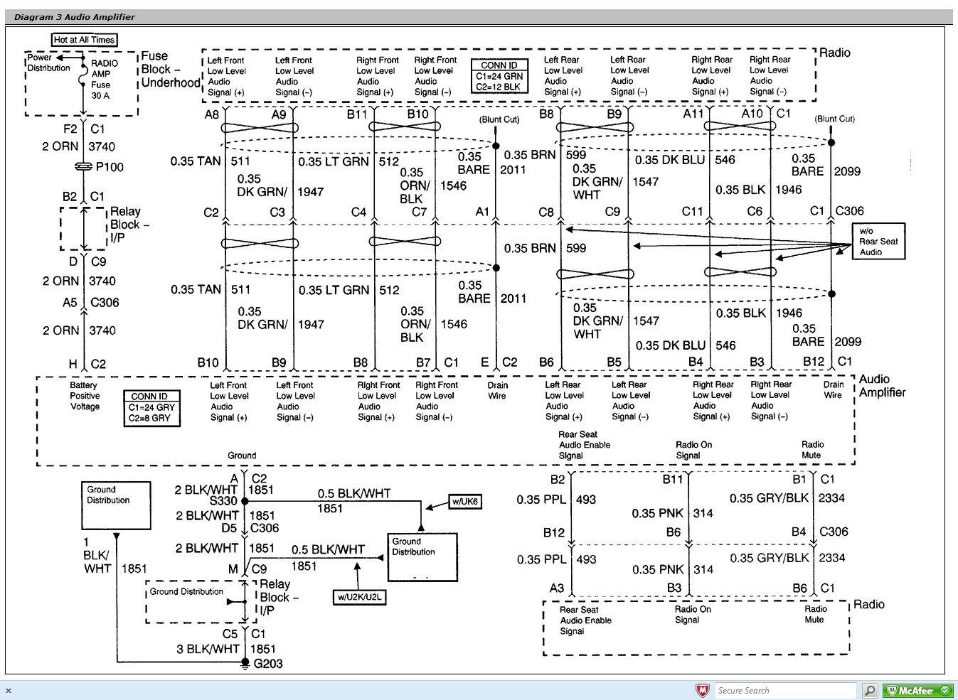
- Connectors: These are the plastic housings that hold the wires together and plug into the back of the radio. They are often color-coded for easy identification. You'll typically find two main connectors: one for power and ground, and another for the speakers.
Symbols: Deciphering the Diagram's Language
Understanding the symbols on the diagram is key to interpreting the wiring layout. Here's a breakdown of common symbols:
- Lines: Represent wires. The thickness of the line can sometimes indicate the wire gauge (thicker lines = thicker wires).
- Colors: Each wire is assigned a specific color, indicated by abbreviations or full names (e.g., RED, BLK, WHT, GRN, BLU, YEL). Some wires may have a stripe, indicated by a slash (e.g., WHT/BLK = white wire with a black stripe).
- Circles or Squares: Represent connectors or terminals.
- GND: Represents ground.
- +12V: Represents a +12 volt power source.
- Arrows: Indicate the direction of current flow.
- Resistors: Represented by a zigzag line.
- Capacitors: Represented by two parallel lines.
- Fuses: Represented by a line with a "C" shape or a simple rectangle with a number indicating its amperage.
The diagram will also show the pinout of the connectors, which indicates the specific wire that is connected to each pin on the connector.
How It Works: Following the Signal Path
The radio receives power from the battery and the ignition switch. When you turn on the ignition, the +12V Switched wire provides power to the radio, and it turns on. The radio then processes the audio signal from the antenna (for radio stations) or from an external source (like your phone). The radio amplifies the audio signal and sends it to the speakers through the speaker wires. The ground wire provides the return path for the electrical current.
Data wires, if present, allow the radio to communicate with other vehicle systems. For example, the steering wheel controls can send signals to the radio to adjust the volume or change the station. The radio can also send signals to the OnStar system to provide information about the vehicle.
Real-World Use: Basic Troubleshooting Tips
Here are some basic troubleshooting tips using the wiring diagram:
- No Power to Radio:
- Check the +12V Constant and +12V Switched wires with a multimeter to ensure they are receiving power.
- Check the ground wire to ensure it is properly grounded.
- Check the fuses associated with the radio in the fuse box.
- No Sound from Speakers:
- Check the speaker wires to ensure they are properly connected to the speakers.
- Check the speaker wires with a multimeter to ensure they are receiving a signal from the radio.
- Test the speakers themselves to ensure they are not blown.
- Static or Interference:
- Check the antenna wire to ensure it is properly connected to the antenna.
- Check the antenna ground.
- Check for loose connections or damaged wiring.
- Dim or no Illumination:
- Check the illumination wire connection.
- Check the fuse associated with the illumination circuit.
Important: Always use a multimeter to test wires before cutting or splicing them. This will help you avoid damaging your vehicle's electrical system.
Safety: Proceed with Caution
Working with electrical systems can be dangerous. Here are some safety precautions to keep in mind:
- Disconnect the Battery: Always disconnect the negative terminal of the battery before working on the electrical system. This will prevent accidental shorts and electric shock.
- Use Proper Tools: Use insulated tools designed for automotive electrical work.
- Avoid Working in Wet Conditions: Water can conduct electricity and increase the risk of electric shock.
- Identify High-Risk Components: Be especially careful when working with the airbag system and other safety-critical components. Incorrect wiring can disable these systems or cause them to deploy unexpectedly.
- Double-Check Your Work: Before reconnecting the battery, carefully double-check your wiring to ensure everything is connected correctly.
Airbags are HIGHLY sensitive devices. If you are uncomfortable working near airbags, consult a professional.
Remember, the wiring harness connects to more than just the radio. Sensors for theft deterrent, airbags and onStar communication might be in proximity.
We have the complete 2008 GMC Sierra Radio Wiring Harness Diagram file available for download. It's a comprehensive resource that will make your audio project much smoother and safer. With this guide and the actual diagram, you'll be well-equipped to tackle your Sierra's audio system with confidence.