2008 Nissan Sentra Fuse Box Diagram
The 2008 Nissan Sentra, while a reliable workhorse, isn't immune to electrical gremlins. Understanding its fuse box diagram is crucial for diagnosing and resolving these issues yourself. This article serves as your guide to navigating the Sentra's fuse system, empowering you to tackle common electrical problems and even plan aftermarket modifications with confidence.
Purpose: Why You Need This Diagram
Why bother diving into the intricacies of the fuse box? Here's a breakdown:
- Troubleshooting Electrical Problems: A blown fuse is often the culprit behind a malfunctioning radio, headlights, power windows, or any other electrical component. The diagram allows you to quickly identify the fuse associated with the affected system.
- Performing Repairs: Replacing a faulty component sometimes requires isolating the circuit. The diagram helps you pinpoint the relevant fuse to disconnect power safely.
- Planning Aftermarket Modifications: Adding accessories like auxiliary lights, a new stereo, or a performance chip requires tapping into the electrical system. The diagram helps you identify appropriate circuits and their amperage ratings, preventing overloads and potential damage.
- Preventative Maintenance: Understanding the fuse layout allows you to periodically inspect fuses for corrosion or signs of wear, potentially preventing future failures.
- General Understanding of Your Vehicle: Knowing the layout of the fuse box is a basic aspect of understanding your car’s electrical system and can lead to more informed maintenance decisions.
Key Specs and Main Parts
The 2008 Nissan Sentra typically has two fuse box locations:
- Interior Fuse Box: Located under the dashboard, usually on the driver's side. This box primarily houses fuses for interior components like the radio, instrument panel, power windows, and interior lighting.
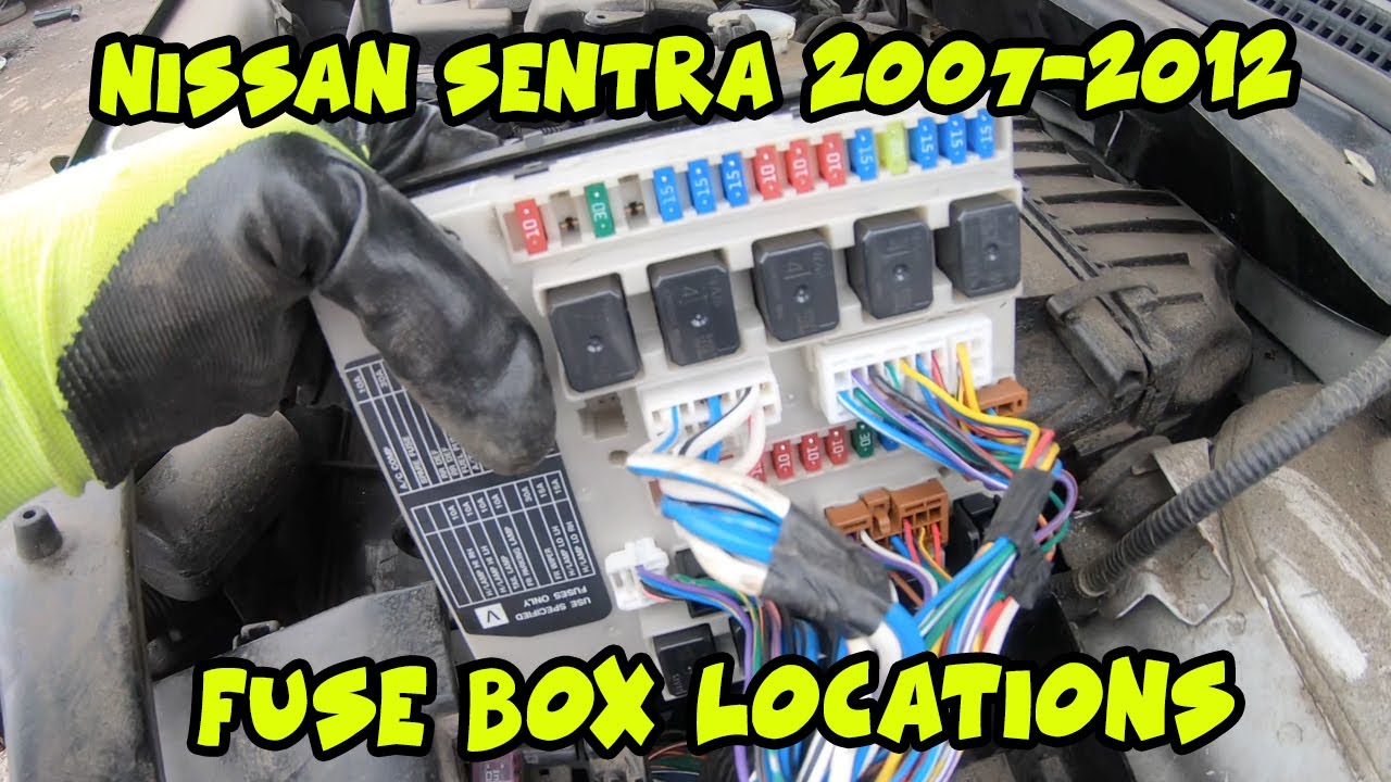
- Engine Compartment Fuse Box: Located in the engine bay, this box contains fuses for critical engine components such as the fuel pump, ignition system, anti-lock braking system (ABS), and headlights.
Within each fuse box, you'll find:
- Fuses: These are the sacrificial components designed to protect circuits from overcurrent. They consist of a thin wire or strip that melts and breaks the circuit when the current exceeds a safe level. Different fuses have different amperage ratings.
- Relays: Relays are electromechanical switches that control high-current circuits using a low-current signal. They're used for components like the headlights, starter motor, and air conditioning compressor.
- Fuse Puller: A small plastic tool included in the fuse box to safely remove and install fuses. Using pliers can damage the fuse and surrounding components.
- Diagram Label: A label, typically located on the inside of the fuse box cover, which shows the location and function of each fuse and relay. This is your primary reference.
Fuse Types: The 2008 Sentra primarily uses blade-type fuses (also known as spade fuses). These come in various sizes and amperage ratings, indicated by their color coding. Common amperage ratings include 5A, 7.5A, 10A, 15A, 20A, 25A, and 30A.
Symbols: Understanding the Diagram
A fuse box diagram isn't just a collection of squares and rectangles; it's a map using specific symbols and conventions. While the exact symbology can vary slightly, here are some common elements:
- Rectangles/Squares: Represent individual fuses. The number inside or next to the rectangle indicates the fuse's amperage rating.
- Circles/Ovals: Typically represent relays.
- Lines: Solid lines indicate direct connections, while dashed lines might represent connections to ground or complex circuits.
- Colors: Fuse colors indicate their amperage rating. It is standardized. For example, a red fuse is typically a 10A fuse. Refer to a color-coding chart if you are unsure.
- Icons: Small icons often depict the component the fuse protects. For example, a headlight icon indicates the headlight circuit, a steering wheel icon may indicate a power steering circuit, and a radio icon indicates the radio circuit.
Abbreviations: The diagram will also use abbreviations for components. Common ones include:
- IGN: Ignition
- ACC: Accessory
- HTR: Heater
- A/C: Air Conditioning
- ENG: Engine
- ECU: Engine Control Unit (the "brain" of the engine)
- ABS: Anti-lock Braking System
How It Works: The Fuse Protection Mechanism
A fuse is a simple but crucial safety device. It contains a thin strip or wire of metal designed to melt and break the circuit if the current flowing through it exceeds its rated amperage. This prevents excessive current from reaching sensitive components, protecting them from damage and preventing potential fires.
When a circuit experiences an overcurrent situation (e.g., due to a short circuit or a malfunctioning component), the fuse element heats up rapidly. If the current is high enough, the element melts, creating an open circuit and stopping the flow of electricity. This "blows" the fuse, protecting the rest of the circuit.
Relays, on the other hand, act as remote-controlled switches. A small current flowing through the relay's coil creates an electromagnetic field, which pulls a switch closed, allowing a larger current to flow through the main circuit. This allows a low-current switch (like a headlight switch on the dashboard) to control a high-current circuit (like the headlights themselves).
Real-World Use: Basic Troubleshooting Tips
Here's a step-by-step guide to troubleshooting electrical problems using the fuse box diagram:
- Identify the Problem: Determine which component isn't working correctly.
- Consult the Diagram: Locate the fuse associated with the malfunctioning component in the fuse box diagram.
- Inspect the Fuse: Use the fuse puller to remove the fuse. Visually inspect it for a broken filament. If the filament is intact, the fuse is likely good. You can also use a multimeter to test continuity across the fuse. A blown fuse will have no continuity.
- Replace the Fuse: If the fuse is blown, replace it with a new fuse of the same amperage rating. Never use a fuse with a higher amperage rating, as this could damage the circuit and create a fire hazard.
- Test the Component: After replacing the fuse, test the component to see if it's now working correctly.
- If the Fuse Blows Again: If the new fuse blows immediately or shortly after replacement, there's likely a short circuit or other underlying problem in the circuit. Further diagnosis is required, potentially involving a mechanic or advanced electrical troubleshooting.
Safety: Handle with Care
Working with electrical systems can be dangerous. Here are some important safety precautions:
- Disconnect the Battery: Before working on any electrical component, disconnect the negative (-) battery cable to prevent accidental shorts and electrical shocks.
- Use the Correct Fuse: Always replace a blown fuse with one of the same amperage rating. Using a higher amperage fuse can overload the circuit and cause a fire.
- Avoid Wet Conditions: Never work on the electrical system in wet or damp conditions.
- Be Aware of High-Voltage Components: The ignition system and certain other components operate at high voltage. Avoid touching these components unless you are properly trained and have the necessary safety equipment.
- If You're Unsure, Seek Professional Help: If you're not comfortable working on the electrical system, consult a qualified mechanic.
Specific High-Risk Components: The engine compartment fuse box often contains fuses and relays related to the fuel pump, ignition system, and ABS. These systems can be complex and potentially dangerous if mishandled. Exercise extreme caution when working with these components.
We have a detailed, printable PDF of the 2008 Nissan Sentra fuse box diagram available for download. This resource will be invaluable for troubleshooting, repairs, and modifications. Please contact us via the contact form on this site, and we can send that to you.