2008 Pontiac G6 Radio Wiring Diagram
Alright, let's dive into the 2008 Pontiac G6 radio wiring diagram. Whether you're tackling a blown fuse, upgrading your head unit, or just trying to understand the electrical heart of your sound system, this diagram is your roadmap. Think of it as a technical blueprint that unveils how power, signals, and speakers are interconnected within your G6.
Purpose and Importance
Why bother with a wiring diagram in the first place? Simple: understanding it can save you time, money, and potential headaches. Here's why:
- Troubleshooting: When your radio suddenly goes silent or a speaker cuts out, the diagram helps you pinpoint the fault. Is it a power issue? A blown fuse? A short in the wiring? The diagram guides your diagnosis.
- Upgrading/Modifying: Swapping the factory head unit for a shiny new aftermarket one? The diagram is crucial for identifying the correct wires for power, ground, speakers, and accessories like remote turn-on for amplifiers.
- Repairing: If a wire is damaged or corroded, the diagram shows you where it connects and the proper wire gauge to use for repairs.
- Learning: Gaining a deeper understanding of your car's electrical system can empower you to perform more complex repairs and modifications in the future.
Key Specs and Main Parts
Before we dissect the diagram, let's familiarize ourselves with the key components of the 2008 Pontiac G6 radio system. Keep in mind that configurations can vary slightly depending on trim level (e.g., base model vs. GT with premium sound).
- Head Unit: The brain of the operation. It receives power, controls the radio tuner, CD player (if equipped), and processes audio signals. It also provides outputs for speakers and other devices.
- Speakers: Front and rear speakers are standard. Higher trim levels might include tweeters and a subwoofer.
- Amplifier (if equipped): Some models have a separate amplifier to boost the audio signal before it reaches the speakers. This is usually located in the trunk or under a seat.
- Wiring Harnesses: Bundles of wires that connect all the components. The main harness plugs into the back of the head unit.
- Fuses: Protect the radio and related circuits from overloads. The radio fuse is usually located in the interior fuse box, but refer to your owner's manual for the exact location and amperage.
- Ground Wires: Provide a return path for electrical current. A good, clean ground connection is essential for proper operation.
- Antenna: Receives radio signals.
- RAP (Retained Accessory Power) Module: This module keeps the radio and other accessories powered on for a short time after the ignition is turned off.
- OnStar Module (if equipped): Integrates with the radio system for hands-free calling and other services.
- Steering Wheel Controls (if equipped): Allow you to control the radio volume, station, and other functions without taking your hands off the wheel. These connect to the head unit via a data bus.
Understanding the Symbols
Wiring diagrams use standardized symbols to represent different components and connections. Let's break down some of the common ones you'll encounter in the 2008 Pontiac G6 radio wiring diagram:
- Solid Lines: Represent wires. The thickness of the line doesn't necessarily indicate wire gauge.
- Dashed Lines: Often indicate shielded wires or data bus connections (like those used for steering wheel controls).
- Circles or Squares with Letters/Numbers: Represent connectors. The letters/numbers identify the specific connector in the vehicle's wiring harness.
- Rectangles: Usually represent components like the head unit, amplifier, or RAP module.
- Zigzag Lines: Represent resistors (which limit current flow).
- Ground Symbol (often looks like an upside-down triangle or a series of parallel lines): Indicates a connection to the vehicle's chassis ground.
- Fuse Symbol: A squiggly line inside a rectangle.
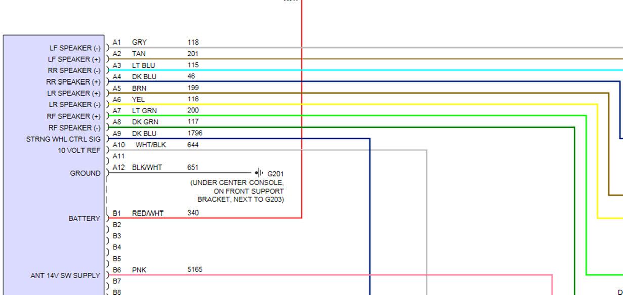
- Color Codes: Each wire in the diagram is typically labeled with a color code (e.g., "RED," "BLK," "GRN/WHT"). This is crucial for identifying the correct wires in the harness. Common color codes include:
- BLK: Black (Ground)
- RED: Red (Power)
- YEL: Yellow (Power)
- GRN: Green
- BLU: Blue
- WHT: White
- BRN: Brown
- ORG: Orange
- GRY: Gray
- Wire Gauge: Often indicated on the diagram next to the wire color. The gauge (e.g., 16 AWG, 18 AWG) specifies the wire's thickness. Use the correct gauge wire when making repairs or modifications.
How It Works: A Simplified Overview
The 2008 Pontiac G6 radio system operates on a relatively straightforward principle. Power from the battery, protected by a fuse, is supplied to the head unit. The head unit processes audio signals from the radio tuner, CD player, or external input (like an auxiliary port). These signals are then amplified (either internally or by a separate amplifier) and sent to the speakers. The speakers convert the electrical signals into sound waves that you hear.
The diagram illustrates this flow, showing the path of each wire from the power source to the speakers and back to ground. It also shows the connections to other systems, like the RAP module and steering wheel controls.
Real-World Use: Basic Troubleshooting
Let's say your radio suddenly stops working. Here's how you might use the wiring diagram to troubleshoot the problem:
- Check the Fuse: Locate the radio fuse in the fuse box. Use the diagram or your owner's manual to identify the correct fuse. If the fuse is blown, replace it with one of the same amperage. If it blows again immediately, there's likely a short circuit somewhere in the wiring.
- Check Power and Ground: Use a multimeter to check for voltage at the head unit's power and ground wires. The diagram shows you which wires to test. If you're not getting power or ground, trace the wires back to the source to identify the break.
- Check Speaker Connections: If only one speaker is not working, check the speaker connections at the speaker itself and at the head unit. The diagram shows you the color-coding of the speaker wires.
- Inspect Wiring Harnesses: Look for any signs of damage, corrosion, or loose connections in the wiring harnesses. Pay particular attention to areas where the wires are exposed to the elements or rubbing against metal parts.
Safety Precautions
Working with automotive electrical systems can be dangerous. Here are some important safety precautions:
- Disconnect the Battery: Always disconnect the negative battery terminal before working on the electrical system. This will prevent accidental short circuits and electrical shocks.
- Use the Right Tools: Use insulated tools designed for automotive electrical work.
- Be Careful with Airbags: Some wiring harnesses may be located near airbag modules. Be extremely careful when working in these areas to avoid accidentally deploying the airbags.
- Never Work on a Live Circuit: Always disconnect the battery before making any repairs or modifications.
- Be Mindful of the PCM (Powertrain Control Module) and other sensitive electronics: Improper wiring can damage these components.
Download the Diagram
Now that you've got a good grasp of the fundamentals, you can put this knowledge to practical use. We have a copy of the complete 2008 Pontiac G6 radio wiring diagram available for you to download. With this detailed resource at your fingertips, you'll be well-equipped to tackle any radio-related electrical challenges your G6 might throw your way. Happy troubleshooting!