2008 Silverado Radio Wiring Harness Diagram
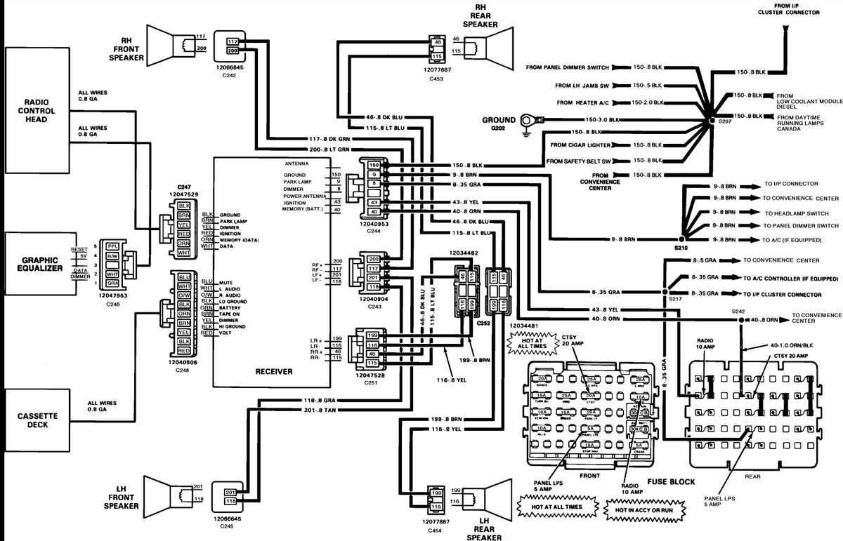
Alright, let's dive into the wiring harness diagram for the 2008 Chevrolet Silverado radio. If you're looking to upgrade your stereo, diagnose a sound issue, or just better understand your truck's electrical system, this diagram is your new best friend. We'll break it down step-by-step, even if you're not an electrical engineer.
Purpose of the 2008 Silverado Radio Wiring Diagram
Why bother with a wiring diagram in the first place? Well, imagine trying to rewire your radio without knowing which wire does what. You'd be asking for trouble! This diagram serves as a road map for the radio's electrical system. Here's why it's so crucial:
- Radio Replacement & Upgrades: Swapping out the factory radio for an aftermarket unit requires connecting the new stereo's wires to the correct wires in the Silverado's harness. The diagram tells you exactly which wire is for power, ground, speakers, antenna, etc.
- Troubleshooting Audio Problems: Is your radio cutting out? Speakers not working? The diagram helps you trace the signal path to identify breaks, shorts, or other issues in the wiring.
- Adding Accessories: Want to install a new amplifier, subwoofer, or backup camera? The wiring diagram shows you where to tap into the existing system for power, signal, and remote turn-on.
- Understanding the System: Even if you're not planning any modifications, the diagram helps you understand how the radio and related components (like the Class 2 data bus we'll talk about later) are interconnected.
Key Specs and Main Parts
Before we crack open the diagram itself, let's go over some essential specs and components:
- Vehicle: 2008 Chevrolet Silverado (Specifically, the 1500, but many diagrams are similar across the 2500 and 3500 models as well). Remember to always verify the diagram matches your specific trim level!
- Radio Type: This often comes in several flavors: Base model (AM/FM radio), CD player, Navigation radio, and radios with Bose premium sound system. The wiring will vary slightly depending on the radio.
- Main Components:
- Radio Head Unit: The brains of the operation.
- Wiring Harness: The bundle of wires connecting the radio to the vehicle's electrical system.
- Speakers: Front left, front right, rear left, rear right (and possibly a subwoofer if equipped).
- Antenna: Receives radio signals.
- Amplifier (if equipped): Boosts the audio signal to the speakers. This is typically only found on models with premium sound systems like Bose.
- OnStar Module (if equipped): Provides communication and navigation services.
- Ground Distribution Blocks: Centralized grounding locations for various circuits.
Understanding the Symbols
A wiring diagram is essentially a symbolic language. Here's how to decipher it:
- Lines: Represent wires. Thicker lines may indicate wires with higher current capacity.
- Colors: Each wire has a specific color code (e.g., Red = Power, Black = Ground, Yellow = Constant Power). The diagram *must* include a color key. Common abbreviations are:
- RD = Red
- BK = Black
- YL = Yellow
- GN = Green
- BL = Blue
- WH = White
- OR = Orange
- TN = Tan
- GY = Gray
- VT = Violet
- Icons:
 This symbol indicates a ground connection (connection to the vehicle's chassis).
- Rectangles often represent components like the radio head unit, amplifier, or speakers.
- Circles with a cross are often used for connectors.
- Diodes look like a triangle pointing at a line – these allow current to flow in only one direction.
- Resistors are shown as a squiggly line.
- Wire Gauges: Sometimes the diagram will indicate the wire gauge (e.g., 16 AWG, 18 AWG). This tells you the thickness of the wire. Higher gauge numbers mean thinner wires.
- Connectors: Diagrams often show the specific connectors used, including pin numbers. This is essential when tapping into existing wiring.
How It Works: The Radio's Electrical Path
The radio wiring is more than just a bunch of wires randomly connected. It’s a carefully designed circuit. Here's a simplified overview:
- Power: The radio needs power to operate. This comes from the vehicle's battery, typically through a fuse. There are usually two power wires:
- Constant Power (+12V): This provides power to retain memory (station presets, clock settings) even when the ignition is off.
- Switched Power (Ignition): This turns the radio on and off with the ignition key.
- Ground: The radio needs a ground connection to complete the circuit. This is usually connected to the vehicle's chassis.
- Speakers: Speaker wires carry the amplified audio signal from the radio to the speakers. Each speaker has a positive (+) and negative (-) wire. Proper polarity is crucial for good sound.
- Antenna: The antenna wire connects the radio to the antenna, which receives radio signals.
- Data Bus (Class 2 or CAN Bus): Modern vehicles use a data bus to communicate between different modules. The radio may use the data bus for functions like steering wheel controls, vehicle speed information (for volume adjustment), and theft deterrent systems. Understanding the data bus is often crucial, but it's also the most complex part. Incorrectly interfacing with the data bus can cause serious problems.
Real-World Use: Basic Troubleshooting Tips
Okay, you've got the diagram. Now what? Here are some common troubleshooting scenarios:
- Radio Not Turning On: Check the fuses first! Then, use a multimeter to verify that the constant power and switched power wires are receiving voltage. Also, check the ground connection.
- No Sound From Speakers: Check the speaker wires for loose connections or damage. Use a multimeter to test the speaker wires for continuity (a complete circuit). If you have an amplifier, make sure it's powered on and working correctly.
- Static or Interference: Check the antenna connection. Make sure the antenna wire is not damaged. Sometimes, aftermarket LED headlights or other electronic devices can cause interference.
- Steering Wheel Controls Not Working: This is likely a data bus issue. Make sure the radio is compatible with the vehicle's data bus system. You may need a special adapter to interface with the data bus.
Safety: Highlighting Risky Components
Working with automotive electrical systems can be dangerous. Here are some safety precautions:
- Disconnect the Battery: Always disconnect the negative terminal of the battery before working on the electrical system. This prevents accidental shorts and electrical shocks.
- Work in a Well-Lit Area: Good lighting helps you see what you're doing and avoid mistakes.
- Use Insulated Tools: Use tools with insulated handles to protect yourself from electrical shocks.
- Be Careful With the Airbag System: Some radio systems are integrated with the airbag system. Incorrectly disconnecting or modifying these wires can disable the airbag system. Refer to the vehicle's service manual for specific instructions.
- Never Cut Wires Randomly: Always identify the wires before cutting them. Use a wiring diagram and a multimeter to verify the wires.
Remember, if you're not comfortable working on the electrical system, it's best to consult a qualified professional. Dealing with the wrong wires, especially within the data bus or airbag systems, could have serious consequences.
We have the full 2008 Silverado Radio Wiring Harness Diagram available for download. It's a valuable resource to keep on hand for any audio-related projects you might undertake. Just be sure to use it responsibly and prioritize safety!