2008 Volvo S60 Dashboard Gauge Cluster Fuse Diagram
The 2008 Volvo S60, while a solid and reliable vehicle, isn't immune to the occasional electrical gremlin. Often, the first place you should look when troubleshooting dashboard issues is the fuse box. Specifically, understanding the fuse diagram for the instrument cluster is crucial. This article will walk you through the intricacies of that diagram, helping you diagnose and potentially fix common problems yourself.
Purpose of the Fuse Diagram
Why bother with a fuse diagram? Several reasons. First and foremost, it’s essential for troubleshooting. If your speedometer, tachometer, fuel gauge, or any other part of your instrument cluster suddenly stops working, a blown fuse is a likely culprit. Replacing the correct fuse is far cheaper and easier than replacing the entire cluster or paying a mechanic for simple diagnosis. Beyond repair, the diagram is also useful for:
- Modification/Adding Accessories: If you're tapping into the vehicle's electrical system to add aftermarket gauges or accessories, you'll need to identify appropriate circuits to avoid overloading them.
- Understanding Your Car: Familiarizing yourself with the fuse layout provides a better understanding of your vehicle's electrical architecture.
- Preventive Maintenance: Regularly checking the condition of your fuses can help identify potential problems before they lead to a breakdown.
Key Specs and Main Parts of the 2008 S60 Instrument Cluster Circuit
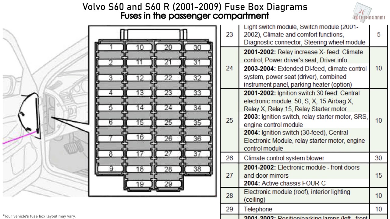
Before diving into the diagram itself, let's establish some basics. The 2008 Volvo S60 has multiple fuse boxes. The one we are concerned with is primarily the one located inside the cabin, often on the driver's side, behind a panel that needs to be removed. There might be another fusebox in the engine compartment.
The instrument cluster itself, also known as the DIM (Driver Information Module) in Volvo terminology, is a complex electronic unit that receives data from various sensors and modules throughout the vehicle via the CAN (Controller Area Network) bus. This data is then processed and displayed on the various gauges and indicators.
Key circuits relating to the instrument cluster typically include:
- Power Supply Fuses: These fuses provide the main power to the cluster, ensuring it can operate.
- CAN Bus Fuses: The CAN bus is the communication network that allows the cluster to receive information from other modules like the ECM (Engine Control Module) and the ABS (Anti-lock Braking System). Fuses protecting these circuits are critical.
- Gauge-Specific Fuses: Some individual gauges or indicators might have their own dedicated fuses.
- Illumination Fuses: These fuses control the backlighting of the instrument cluster, allowing you to see the gauges at night.
Understanding the Symbols on the Fuse Diagram
Fuse diagrams use a standardized set of symbols and conventions to represent different components and circuits. Here's a breakdown of common symbols you'll encounter:
- Lines: Solid lines typically represent wires, while dashed lines can indicate shielded wires or connections to ground.
- Rectangles: Usually denote fuses. A rectangle with a number inside indicates the fuse's amperage rating (e.g., 10 inside the rectangle means a 10-amp fuse).
- Circles: Represent components, often simplified representations of relays, sensors, or actuators.
- Colors: Wire colors are often indicated using abbreviations (e.g., "RD" for red, "BL" for blue, "BK" for black, "GN" for green, "YW" for yellow, "VT" for violet). These colors are crucial for tracing wires and identifying specific circuits.
- Icons: Specific icons might represent different components, such as a speedometer needle for the speedometer circuit or a fuel pump symbol for the fuel gauge circuit. Consult the specific legend provided with your diagram to understand these icons.
It's vital to note that Volvo's fuse diagrams often include a numerical index corresponding to a list of fuse descriptions. Always refer to this index to accurately identify the function of each fuse.
How It Works: From Fuse to Function
Let's trace a simplified example. Imagine the speedometer stops working. Your first step is to locate the fuse diagram. After identifying the fuse labeled as "Instrument Cluster/Speedometer," you'd physically locate that fuse in the fuse box. If the fuse is blown (the small wire inside is broken), you replace it with a fuse of the same amperage rating. If the speedometer works again, the problem is solved. If the fuse blows again immediately, or shortly after, there's a short circuit somewhere in the speedometer circuit that needs further investigation.
The crucial concept here is that the fuse acts as a sacrificial element. It's designed to break the circuit and protect more expensive and sensitive components (like the instrument cluster itself) from damage due to excessive current flow caused by a short circuit or overload.
Volvo's system is a distributed control system. The instrument cluster doesn’t directly receive signals from all sensors. Instead, sensors send data to control modules (like the ECM or ABS module). These modules then transmit the data over the CAN bus, which the instrument cluster interprets and displays. Therefore, a malfunctioning gauge could indicate a problem with the gauge itself, the module sending the data, the CAN bus communication, or the power supply to any of these components.
Real-World Use: Basic Troubleshooting Tips
Here's a basic troubleshooting workflow for common instrument cluster issues:
- Identify the Problem: Which gauge(s) or indicator(s) are not working?
- Consult the Fuse Diagram: Locate the diagram (usually in your owner's manual or online - *we have a copy available for download at the end of this article*). Identify the fuses associated with the affected component(s).
- Inspect the Fuses: Physically remove the fuses and inspect them. Look for a broken filament inside the fuse. A blown fuse will have an obvious break.
- Replace the Fuse: If a fuse is blown, replace it with a fuse of the exact same amperage rating. Using a higher amperage fuse can damage the circuit.
- Test: Turn on the ignition and check if the problem is resolved.
- If the Fuse Blows Again: There's a short circuit in the circuit. This requires further investigation, potentially involving tracing wires and checking for damaged insulation. This is where a multimeter and wiring diagram become essential. Consult a qualified technician if you're not comfortable with electrical troubleshooting.
- If the Fuse Isn't Blown: The problem may lie elsewhere, such as a faulty sensor, a malfunctioning control module, or a problem with the CAN bus communication. Further diagnostics are required.
Safety Considerations
Working with automotive electrical systems can be dangerous. Always follow these safety precautions:
- Disconnect the Battery: Before working on any electrical circuits, disconnect the negative (-) terminal of the battery. This prevents accidental short circuits and potential electrocution.
- Use Proper Tools: Use insulated tools designed for automotive electrical work.
- Never Exceed Fuse Ratings: Always replace blown fuses with fuses of the exact same amperage rating. Using a higher amperage fuse can overload the circuit and cause a fire.
- Be Aware of Airbag Circuits: Airbag circuits are highly sensitive. Avoid probing or disconnecting connectors in the airbag system unless you have the proper training and equipment. Airbags can deploy unexpectedly, causing serious injury.
- Capacitors: Some electronic components, like those within the instrument cluster, can store electrical charge even after the battery is disconnected. Be cautious when handling these components.
Important Note: While replacing a blown fuse is often a simple fix, repeated fuse failures indicate a more serious underlying problem. Don't simply keep replacing fuses without investigating the cause of the short circuit. This can damage expensive components and potentially create a fire hazard.
Navigating automotive electrical systems can seem daunting, but armed with the right information and a methodical approach, you can tackle many common issues yourself. Remember to always prioritize safety and consult a qualified technician when dealing with complex or potentially dangerous electrical problems.
We understand how crucial it is to have the correct reference materials, especially when troubleshooting electrical issues. We have the 2008 Volvo S60 Dashboard Gauge Cluster Fuse Diagram available for download. Use it as a valuable aid in your diagnostic endeavors.