
2009 Chevy Malibu Exhaust System Diagram
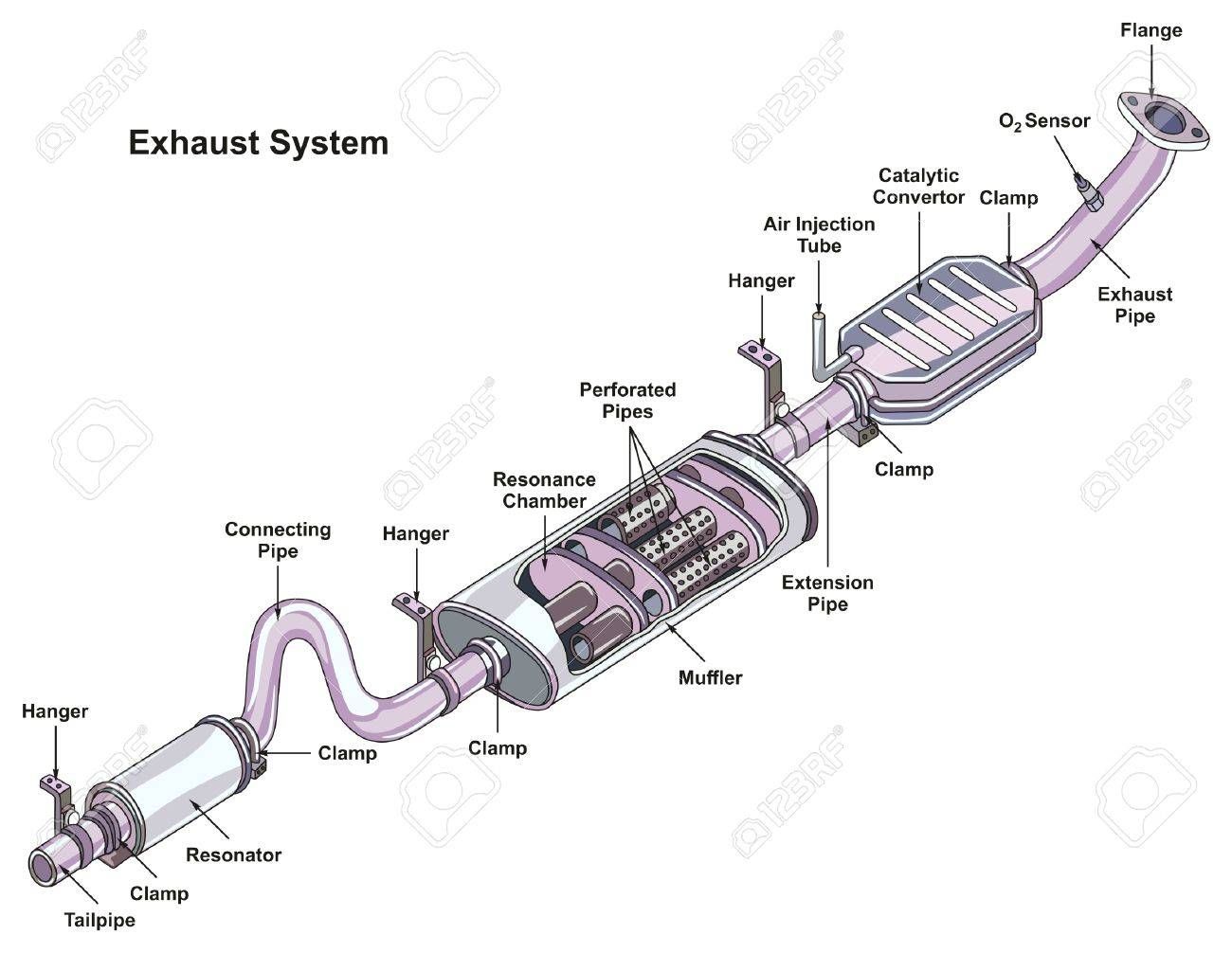
Alright, let's dive into the exhaust system diagram for the 2009 Chevy Malibu. This isn't just a pretty picture; it's your roadmap to understanding, diagnosing, and potentially repairing one of the most critical (and often neglected) systems on your car. Whether you're chasing down that annoying rattle, prepping for a performance upgrade, or just trying to get a better grip on automotive mechanics, understanding the exhaust system is crucial. And having the diagram – which we can provide – makes it all that much easier.
Why This Diagram Matters
Why bother with an exhaust system diagram? Several reasons:
- Troubleshooting: Identifying the source of exhaust leaks, strange noises, or performance issues becomes *far* easier when you can visualize the entire system. A diagram helps pinpoint the exact component that's failing.
- Repair and Replacement: Knowing the layout and part names allows you to order the correct replacement parts. Imagine trying to replace a "resonator" when you thought it was a "catalytic converter"! A diagram eliminates that guesswork.
- Modification and Upgrades: Planning an exhaust upgrade? The diagram shows you the factory layout, dimensions (roughly), and connection points. This is invaluable when selecting aftermarket parts or designing a custom exhaust system.
- Learning: Simply understanding how the exhaust system works provides a foundation for more advanced automotive knowledge. It's a building block.
Key Specs and Main Parts of the 2009 Malibu Exhaust
The 2009 Malibu's exhaust system, in its simplest form, directs exhaust gases away from the engine and reduces harmful emissions. Here’s a breakdown of the key components:
- Exhaust Manifold(s): Bolted directly to the engine's cylinder head(s), the manifold collects exhaust gases from each cylinder. The 2009 Malibu, depending on the engine (2.4L I4 or 3.6L V6), will have either one or two manifolds. The V6 models have two manifolds, one for each bank of cylinders.
- Catalytic Converter(s): This is where the magic happens (or at least the chemical reactions). The catalytic converter uses catalysts (platinum, palladium, rhodium) to convert harmful pollutants (hydrocarbons, carbon monoxide, and nitrogen oxides) into less harmful substances (water, carbon dioxide, and nitrogen). Malibus typically have one or two catalytic converters, depending on the engine and emissions package. A faulty catalytic converter can trigger the "check engine" light and cause performance issues.
- Oxygen Sensors (O2 Sensors): These sensors monitor the amount of oxygen in the exhaust stream. They are located both before (upstream) and after (downstream) the catalytic converter. The upstream sensor provides feedback to the engine control unit (ECU) to optimize fuel mixture. The downstream sensor monitors the efficiency of the catalytic converter.
- Resonator: A resonator is a chamber designed to cancel out certain frequencies of sound, reducing exhaust noise. It's typically located in the middle of the exhaust system.
- Muffler: The muffler is the main noise reduction device in the exhaust system. It uses a series of chambers and tubes to dampen sound waves.
- Exhaust Pipes: These are the pipes that connect all the components together. They are typically made of steel or stainless steel.
- Hangers and Mounts: These rubber or metal supports secure the exhaust system to the undercarriage of the car, preventing it from vibrating and causing damage.
- Flanges and Gaskets: Flanges are the bolted connections between exhaust components, and gaskets are used to seal these connections and prevent exhaust leaks. Exhaust leaks are a common problem and can lead to reduced fuel economy and performance.
Understanding Diagram Symbols
The exhaust system diagram will use a specific set of symbols and conventions. Here's what you need to know:
- Lines: Solid lines generally represent exhaust pipes. Thicker lines might indicate larger diameter pipes. Dashed lines could indicate vacuum lines associated with emissions control (though less common directly on the exhaust itself on a Malibu).
- Component Outlines: Each component (catalytic converter, muffler, etc.) will have a distinct shape. The diagram *should* include a key or legend that identifies each shape.
- Arrows: Arrows indicate the direction of exhaust flow. This is critical for understanding how the system is designed to work.
- Fasteners: Bolts, nuts, and clamps are usually represented by small circles or squares. Pay attention to these, as they're potential points of failure (rust, corrosion, loosening).
- O2 Sensor Symbols: Oxygen sensors are typically represented by a symbol resembling a light bulb or a circle with a wire coming out of it. The diagram should clearly indicate which sensor is upstream and which is downstream.
- Colors: While not always present in all diagrams, color coding, if used, can denote pipe material (e.g., stainless steel vs. aluminized steel) or temperature zones.
How the Exhaust System Works
The exhaust system's operation is pretty straightforward, but understanding the sequence is key to diagnosing issues:
- Exhaust Gases Exit the Engine: Hot exhaust gases, the byproduct of combustion, are forced out of the engine cylinders and into the exhaust manifold(s).
- Catalytic Conversion: The exhaust gases then flow into the catalytic converter(s). Here, the catalyst promotes chemical reactions that convert harmful pollutants into less harmful substances. This is a heat-intensive process, which is why catalytic converters get so hot.
- Oxygen Sensor Feedback: Oxygen sensors monitor the exhaust gas composition before and after the catalytic converter. This information is sent to the ECU, which adjusts the air-fuel mixture to optimize engine performance and emissions.
- Resonance Reduction: The resonator, if equipped, dampens specific sound frequencies to reduce noise levels.
- Muffling: The muffler further reduces noise by channeling exhaust gases through a series of chambers and tubes.
- Exhaust to Atmosphere: Finally, the exhaust gases are expelled into the atmosphere through the tailpipe.
Real-World Use: Basic Troubleshooting Tips
Here are a few common problems you might encounter and how the exhaust diagram can help:
- Exhaust Leak: Listen for a hissing or chugging sound, especially when the engine is cold. The diagram helps you visually inspect the flanges, gaskets, and pipes for cracks or corrosion. Feel (carefully!) for escaping exhaust gases. Never touch a hot exhaust system.
- Rattling Noise: A rattling noise could indicate a loose heat shield, a broken hanger, or a detached component inside the muffler. The diagram helps you locate and inspect these components.
- Check Engine Light (P0420 Code): This code often indicates a problem with the catalytic converter or the oxygen sensors. The diagram helps you identify the location of these components and understand their relationship to each other. Use an OBD-II scanner to read the codes and research their specific meaning.
- Reduced Performance: A clogged catalytic converter or a significant exhaust leak can restrict exhaust flow and reduce engine performance. The diagram helps you visualize the exhaust flow path and identify potential restrictions.
Safety First!
Working on the exhaust system presents several safety hazards:
- Heat: Exhaust components can get *extremely* hot, especially after the engine has been running. Allow the system to cool completely before working on it.
- Burns: Even a slightly warm exhaust pipe can cause burns. Wear appropriate gloves and long sleeves.
- Exhaust Gases: Exhaust gases contain harmful substances, including carbon monoxide. Work in a well-ventilated area.
- Jacking Up the Car: Always use jack stands when working under a car. Never rely solely on the jack.
- Eye Protection: Wear safety glasses to protect your eyes from debris and rust.
Working on the exhaust system can be challenging, but with the right tools, knowledge, and safety precautions, it's a manageable task for the experienced DIYer. The 2009 Chevy Malibu exhaust system diagram is your essential guide. Remember to be thorough, double-check your work, and prioritize safety above all else. And of course, when in doubt, consult a professional mechanic.
We have the file. Reach out, if you need one.