2009 Chrysler Town And Country Fuse Box Diagram
Alright, let's dive into the fuse box diagram for a 2009 Chrysler Town and Country. This is a crucial piece of information for anyone who likes to tinker with their vehicle, perform basic repairs, or even just understand how its electrical systems are protected. Consider this your comprehensive guide, explained in a way that's accessible even if you're not a seasoned electrician.
Purpose of the Fuse Box Diagram
The fuse box diagram serves as a roadmap to your vehicle's electrical protection system. Without it, troubleshooting electrical issues becomes a frustrating guessing game. Here's why it's important:
- Troubleshooting Electrical Problems: If your headlights aren't working, your radio is dead, or any other electrical component malfunctions, the first thing you should check is the relevant fuse. The diagram tells you exactly which fuse controls that circuit.
- Identifying Circuit Loads: Understanding which fuse protects which component gives you insight into the vehicle's electrical system design. This is particularly useful if you're planning on adding aftermarket accessories.
- Preventing Further Damage: A blown fuse is a sign that a circuit is overloaded or shorted. Replacing a fuse without understanding the underlying problem can lead to further damage to components and even electrical fires. The diagram helps you identify potential problem areas.
- Learning the System: For DIY enthusiasts, studying the fuse box diagram is a great way to understand the general layout of the electrical systems, and how different components work together.
Key Specs and Main Parts of the Fuse Box
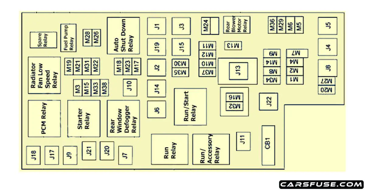
The 2009 Chrysler Town and Country typically has two main fuse boxes: one located under the hood (the Power Distribution Center or PDC) and another inside the cabin, usually on the driver's side. Here's what you need to know:
- Under-Hood Fuse Box (PDC): This box houses fuses and relays for high-current systems like the engine control module (ECM), starter motor, headlights, and power windows. Because these systems draw higher current, the fuses and relays tend to be larger.
- Interior Fuse Box: This box typically manages lower-current circuits such as the radio, interior lights, power door locks, and instrument panel.
- Fuses: These are the sacrificial elements designed to break the circuit when the current exceeds a safe level. Fuses are rated in amperes (amps), which indicates the amount of current they can handle before blowing. Common fuse types include blade fuses (ATO, ATC, mini, and low-profile mini) and cartridge fuses.
- Relays: These are electrically operated switches that control high-current circuits using a low-current signal. Relays are essential for controlling devices like headlights and starter motors without overloading the switch circuit.
- Fuse Puller: A small plastic tool used to safely remove fuses without damaging them or yourself.
- Test Light or Multimeter: A test light or multimeter is used to verify continuity (whether a circuit is complete) across a fuse. A blown fuse will have no continuity.
Understanding the Symbols on the Diagram
The fuse box diagram isn't just a list of numbers; it uses symbols and conventions to represent different components and circuits. Here's a breakdown of common symbols:
- Lines: Lines represent the electrical circuits. Thicker lines often indicate higher current-carrying capacity.
- Boxes: Boxes typically represent fuses or relays. The number inside the box corresponds to the fuse or relay number on the physical fuse box.
- Color Codes: Different colored wires indicate different circuits or functions. While the diagram might not explicitly show wire colors, knowing common color codes can be helpful:
- Red: Typically indicates a power wire (positive voltage).
- Black: Usually indicates a ground wire (negative voltage or return path).
- Other Colors: Indicate various signal wires or circuits. Refer to a full wiring diagram for complete color coding.
- Icons: Icons represent the component that the fuse protects. For example:
- A headlight icon indicates the headlight circuit.
- A radio icon indicates the radio circuit.
- A fan icon might indicate the cooling fan circuit.
The diagram will also include a table or legend that lists each fuse or relay number, its amperage rating, and the component it protects. This is the key to understanding the entire system.
How the Fuse Box Works: A Simple Explanation
Think of the fuse box as a central distribution point for electrical power, with each circuit having its own "gatekeeper" (the fuse). When everything is normal, electricity flows freely through the fuse to the component it powers. If there's a surge in current (due to a short circuit or overload), the fuse's internal element melts, breaking the circuit and stopping the flow of electricity. This prevents damage to the component and the wiring. The amperage rating of the fuse is crucial. Using a fuse with a higher rating than specified can bypass the protection and cause significant damage or even a fire hazard.
Relays act as remote-controlled switches. A small current from a switch inside the car energizes the relay's coil, which then closes a set of contacts, allowing a larger current to flow to the component. This allows you to control high-power devices with a low-power switch, preventing the switch from burning out.
Real-World Use: Basic Troubleshooting Tips
Let's say your interior lights aren't working. Here's how you'd use the fuse box diagram to troubleshoot the problem:
- Consult the Diagram: Locate the interior fuse box diagram (either in your owner's manual or the downloadable file we provide).
- Identify the Fuse: Find the fuse labeled "Interior Lights" or something similar. Note its number and amperage rating.
- Locate the Fuse: Open the interior fuse box and find the fuse you identified.
- Inspect the Fuse: Visually inspect the fuse. If the small wire inside is broken, the fuse is blown.
- Test the Fuse: If you can't visually confirm, use a test light or multimeter to check for continuity. Connect the test light to a known good ground, and then touch the test points on top of the fuse (with the ignition OFF). If the test light doesn't illuminate, or the multimeter shows no continuity, the fuse is blown.
- Replace the Fuse: Replace the blown fuse with a new fuse of the exact same amperage rating.
- Test the System: Turn on the interior lights to see if they now work.
- If the Fuse Blows Again: If the new fuse blows immediately, there's a short circuit or overload in the interior lights circuit. Further investigation is required to find the source of the problem. This might involve checking the wiring, sockets, and bulbs for damage.
Safety First: Identifying and Handling Risky Components
Working with electrical systems can be dangerous. Here are some important safety precautions:
- Disconnect the Battery: Before working on any electrical system, disconnect the negative battery cable to prevent accidental short circuits.
- Never Bypass a Fuse: Never replace a fuse with a higher amperage fuse or use a wire or other conductive material to bypass the fuse. This can cause severe damage and fire hazards.
- Be Careful Around High-Voltage Components: Components like the ignition coil and alternator can generate high voltage even after the engine is turned off. Avoid touching these components unless you know what you're doing.
- Use Insulated Tools: Use tools with insulated handles to protect yourself from electrical shock.
- If You're Unsure, Consult a Professional: If you're not comfortable working with electrical systems, take your vehicle to a qualified mechanic.
Specifically regarding the 2009 Town and Country: Be extra cautious around the ABS system and the airbags. Incorrectly handling these systems can lead to serious injury.
We have a copy of the 2009 Chrysler Town and Country fuse box diagram available for download. This will be a much more detailed and accurate resource than any generalized information you find online. It includes both the under-hood and interior fuse box layouts, fuse numbers, amperage ratings, and component descriptions.
Disclaimer: This information is for educational purposes only and should not be considered a substitute for professional advice. Always consult with a qualified mechanic or electrician before performing any repairs or modifications to your vehicle. Working with electrical systems can be dangerous, and you are responsible for your own safety.