2009 Dodge Ram 2500 Fuse Box Diagram
Alright folks, let's dive into the heart of your 2009 Dodge Ram 2500's electrical system: the fuse box. This article will serve as your comprehensive guide to understanding its diagram, helping you diagnose electrical issues, perform modifications, and generally become more familiar with your truck's inner workings. Knowing your way around the fuse box is invaluable for any serious DIYer, saving you time, money, and the headache of a trip to the mechanic for simple fixes.
Purpose of Understanding the Fuse Box Diagram
Why bother learning this stuff? Well, the fuse box is essentially the central protection system for your truck's electrical components. Each fuse is a sacrificial link, designed to break the circuit if the current draw exceeds a safe level. This prevents damage to more expensive components like the ECU (Engine Control Unit), lighting systems, and other electronic modules. Having a solid understanding of the fuse box diagram enables you to:
- Troubleshoot electrical problems: Is your radio dead? Tail lights not working? The fuse box is the first place to check.
- Perform modifications: Adding aftermarket lights, amplifiers, or other accessories requires tapping into the electrical system safely, which often involves using a fuse tap or dedicated circuit.
- Prevent further damage: Identifying a blown fuse quickly can prevent further damage to connected components.
- Understand your vehicle's electrical system: Gaining knowledge about how the electrical circuits function.
Key Specs and Main Parts
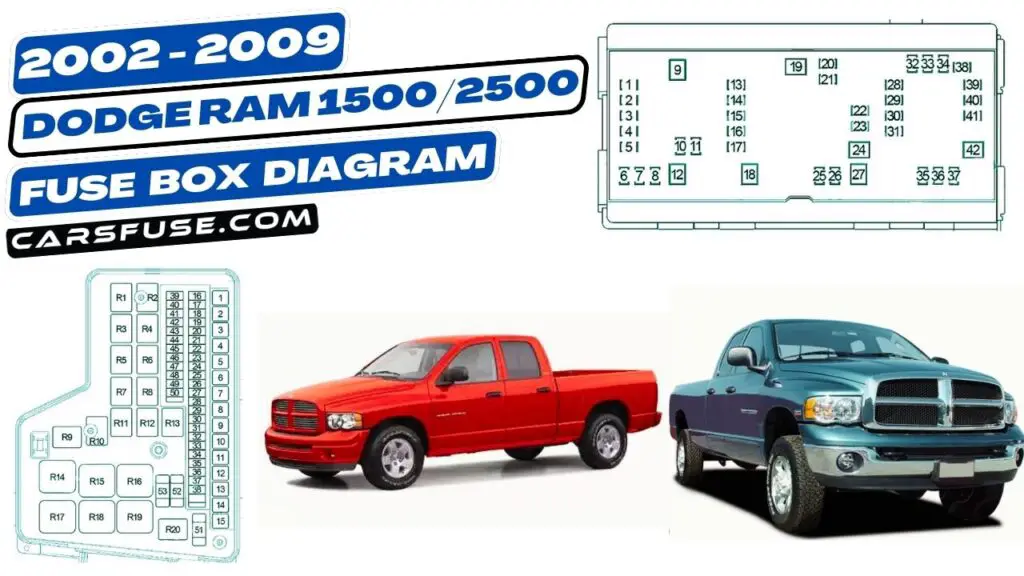
The 2009 Dodge Ram 2500 typically has two main fuse box locations:
- Power Distribution Center (PDC): Located under the hood, this box houses larger fuses and relays that control high-current components like the starter motor, alternator, and cooling fans.
- Interior Fuse Box: Usually found on the driver's side, either under the dashboard or behind a small access panel. This box contains fuses for interior lights, radio, power windows, and other accessories.
The diagram itself will detail the location of each fuse and relay within these boxes. You'll see labels like "M10", "F22", or "R3", corresponding to specific components. It's crucial to have the correct diagram for your specific model year (2009) and trim level, as fuse assignments can vary.
Key Components to Note:
- Fuses: Available in different amperage ratings (e.g., 5A, 10A, 20A, 30A). The amperage rating indicates the maximum current the fuse can handle before blowing. They are typically color-coded for easy identification.
- Relays: Electrically operated switches that control high-current circuits using a low-current signal. They are used to protect switches and wiring from high current loads.
- Jumpers: Used to configure different options.
- Spare Fuses: Usually, there are a few spare fuses with different amperages available.
Understanding Fuse Box Symbols
The fuse box diagram isn't just a random assortment of numbers and letters; it uses standardized symbols to represent different components and their functions. Here's a breakdown of common symbols:
- Lines: Solid lines generally represent wiring connections. Dashed lines may indicate optional or less common connections. Line thickness can sometimes indicate the wire gauge (thicker lines for higher current circuits).
- Colors: Wire colors are crucial for tracing circuits. The diagram should include a color code legend. Common colors include Red (typically power), Black (ground), and various other colors for signal wires.
- Fuse Symbol: Usually depicted as a squiggly line between two connection points. The amperage rating is often indicated next to the symbol (e.g., 20A).
- Relay Symbol: A relay is typically shown as a coil and a switch. The coil represents the electromagnet that activates the switch.
- Ground Symbol: Indicates a connection to the vehicle's chassis, providing a return path for the current.
- Component Icons: These symbols represent specific components like headlights, taillights, the radio, or the windshield wiper motor.
Understanding these symbols will allow you to visually trace circuits and identify the components connected to a specific fuse or relay.
How It Works: The Electrical Circuit
To truly understand the fuse box, you need to grasp the concept of an electrical circuit. A circuit is a closed loop that allows electrical current to flow from a power source (the battery) to a load (a light bulb, motor, etc.) and back to the power source. The fuse is placed in this circuit to protect it from overcurrent situations.
When the current in a circuit exceeds the fuse's amperage rating, the fuse's internal element melts, breaking the circuit and stopping the flow of current. This prevents overheating and potential damage to wiring and components. Think of it as a circuit breaker in your home's electrical panel, but on a smaller scale.
The relay works differently. It uses a small amount of current to activate a switch that controls a larger amount of current. This is useful when the switch needs to be located far away from the device it controls, or when the device requires a lot of power. For example, the headlights are often controlled by a relay because they require a lot of power, and the switch needs to be easily accessible to the driver.
Real-World Use: Basic Troubleshooting Tips
Here's how you can use the fuse box diagram to troubleshoot common electrical problems:
- Identify the Problem: What's not working? Be specific.
- Consult the Diagram: Locate the fuse or relay associated with the affected component in the fuse box diagram.
- Inspect the Fuse: Remove the fuse using a fuse puller (a small plastic tool designed for this purpose) and visually inspect it. A blown fuse will have a broken or melted filament.
- Test the Fuse: Even if the fuse *looks* okay, it's best to test it with a multimeter. Set the multimeter to continuity mode (usually indicated by a diode symbol or a sound). Place the probes on both ends of the fuse. If the multimeter beeps or shows a reading close to zero, the fuse is good. If it shows "OL" or a high resistance, the fuse is blown.
- Replace the Fuse: Replace the blown fuse with a new fuse of the same amperage rating. Never use a fuse with a higher amperage rating, as this could overload the circuit and cause serious damage or a fire.
- Test the Circuit: After replacing the fuse, test the affected component to see if it now works. If the fuse blows again immediately, there's a short circuit or overload in the circuit that needs to be diagnosed and repaired.
- Check the Relay: If a component isn't working, and its fuse is fine, the relay might be the problem. Relays can fail due to worn contacts or a faulty coil. Testing relays typically involves using a multimeter to check for continuity and voltage.
Safety Considerations
Working with electrical systems can be dangerous. Always follow these safety precautions:
- Disconnect the Battery: Before working on any electrical components, disconnect the negative (-) battery terminal to prevent accidental shorts and electrical shocks.
- Use the Right Tools: Use insulated tools to prevent shocks. A multimeter is essential for diagnosing electrical problems.
- Never Bypass a Fuse: Never replace a fuse with a wire or other conductive material. This bypasses the protection mechanism and can lead to a fire.
- Be Careful with High-Current Circuits: The circuits associated with the starter motor, alternator, and cooling fans carry high currents and can deliver a powerful shock. Exercise extreme caution when working with these circuits.
- Properly Ground: When adding modifications, ensure you ground appropriately. Poor grounding can lead to electrical noise, component malfunction, or even damage.
Specifically, the Power Distribution Center (PDC) under the hood contains circuits with very high amperage. Accidental shorts here can cause sparks, burns, and even battery explosions. Treat this area with the utmost respect.
Understanding the 2009 Dodge Ram 2500 fuse box diagram empowers you to tackle electrical issues with confidence. Remember to consult the diagram frequently, use the right tools, and prioritize safety. With a little practice, you'll be able to diagnose and repair many common electrical problems yourself, saving time and money. We have the file for the 2009 Dodge Ram 2500 fuse box diagram that is discussed in this article available for download. It should provide the reference information required for maintaining your vehicle.