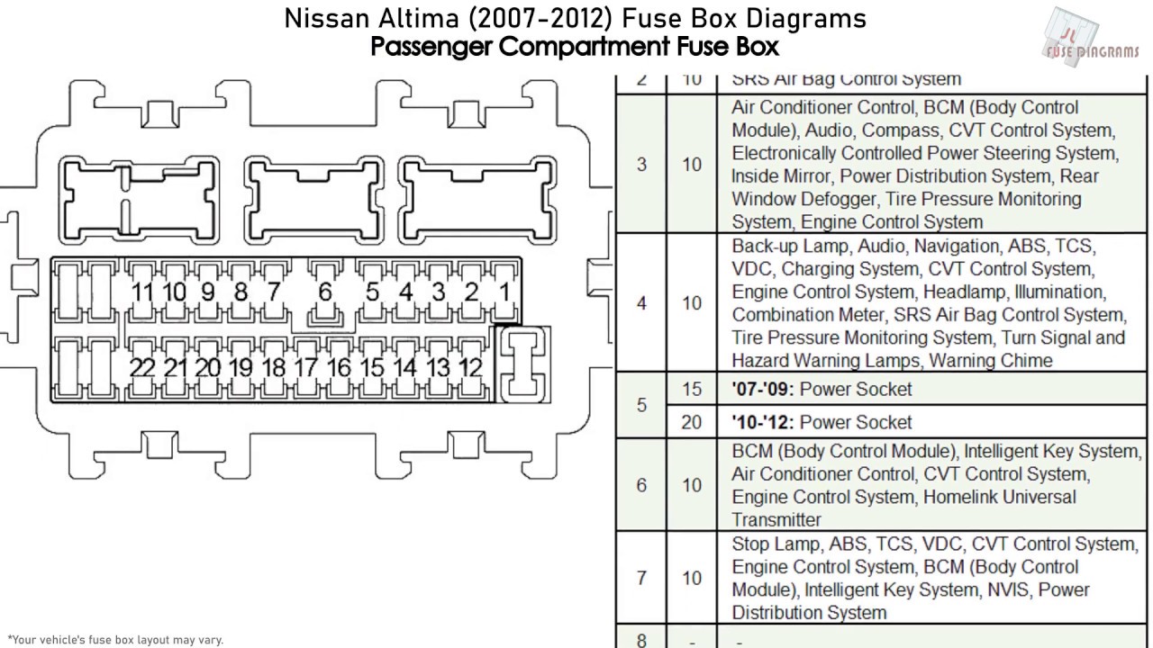
2009 Nissan Altima Fuse Box Diagram
For the seasoned DIYer, a good understanding of your vehicle's electrical system is crucial. And at the heart of that system lies the fuse box. This article delves into the 2009 Nissan Altima fuse box diagram, providing a detailed guide to understanding its components, function, and troubleshooting techniques. Whether you're performing routine maintenance, diagnosing electrical issues, or even planning modifications, this knowledge will prove invaluable.
Purpose of Understanding the Fuse Box Diagram
Why bother with a fuse box diagram? Well, its utility extends far beyond simply replacing a blown fuse. Here's why it's a must-have resource:
- Fault Diagnosis: The diagram helps you quickly identify the correct fuse or relay associated with a malfunctioning component. This saves time and prevents you from aimlessly checking every fuse in the box.
- Preventative Maintenance: Understanding the layout allows you to periodically inspect fuses for corrosion or signs of overheating, potentially preventing future electrical failures.
- Modification and Upgrades: Planning to add aftermarket accessories like a new stereo, lighting, or performance parts? The diagram shows you where to safely tap into the vehicle's electrical system without overloading circuits.
- Educational Value: Deepening your understanding of your vehicle's electrical architecture builds your confidence and skills as a DIY mechanic.
In essence, the fuse box diagram is your roadmap to navigating the complex electrical landscape of your 2009 Altima.
Key Specs and Main Parts
The 2009 Nissan Altima, like most modern vehicles, has multiple fuse boxes, typically located in the following areas:
- Inside the Passenger Compartment: Usually under the dashboard, near the steering column or in the glove compartment. This box primarily houses fuses for interior components like lights, radio, power windows, and the climate control system.
- Under the Hood (Engine Bay): This box contains fuses and relays for essential engine management systems, headlights, horn, anti-lock braking system (ABS), and other critical functions.
Key Components:
- Fuses: Sacrificial devices designed to protect circuits from overcurrent. They contain a thin wire that melts and breaks the circuit when the current exceeds a predetermined level. Fuses are rated in Amperes (Amps), indicating the maximum current they can handle.
- Relays: Electrically operated switches that allow a low-current circuit to control a high-current circuit. For example, the starter relay allows the ignition switch (low current) to activate the starter motor (high current).
- Fuse Puller: A small plastic tool included in the fuse box for safely removing fuses. Avoid using metal objects, as this can damage the fuse box and potentially cause a short circuit.
- Test Light or Multimeter: Essential tools for verifying if a fuse is blown and for testing the continuity of circuits. A multimeter can measure voltage, current, and resistance, providing more detailed diagnostic information.
Understanding Fuse Box Symbols
The fuse box diagram utilizes a set of symbols and notations to represent different components and their functions. Familiarizing yourself with these symbols is crucial for accurate interpretation.
- Lines: Solid lines represent conductors or wires, while dotted lines may indicate shielded wires or ground connections. The thickness of the line generally doesn't represent the wire gauge in these simplified diagrams.
- Colors: Wire colors are typically indicated on the diagram, often using abbreviations (e.g., BLU for blue, RED for red, GRN for green). These colors help you identify the correct wire when troubleshooting.
- Icons: Specific icons represent different components. Common icons include:
- A light bulb icon for lights (headlights, taillights, interior lights).
- A speaker icon for the audio system.
- A fan icon for the cooling fan or blower motor.
- A steering wheel icon for power steering.
- A battery icon for the battery circuit.
- A squiggly line inside a rectangle for relays.
- Ampere Rating: Each fuse location on the diagram is labeled with its corresponding Ampere (A) rating. Always replace a blown fuse with one of the same Ampere rating. Using a higher-rated fuse can damage the circuit and potentially start a fire.
How It Works: From Battery to Component
The fuse box acts as a central distribution point for electrical power. Power flows from the battery, through the ignition switch, and then to the fuse boxes. Each fuse protects a specific circuit. If a component draws excessive current (e.g., due to a short circuit or malfunction), the corresponding fuse blows, interrupting the circuit and preventing damage to the wiring and components. Relays, controlled by low-current circuits, act as switches to control high-current devices. For example, when you turn on your headlights, a low-current circuit from the headlight switch activates the headlight relay, which then allows high-current power to flow to the headlights.
Real-World Use: Basic Troubleshooting Tips
Here's how to use the fuse box diagram for basic troubleshooting:
- Identify the Problem: Determine which component is not working (e.g., the radio, the power windows, the headlights).
- Consult the Diagram: Locate the fuse or relay associated with the malfunctioning component on the fuse box diagram. Refer to the correct fuse box location (passenger compartment or engine bay).
- Inspect the Fuse: Visually inspect the fuse. If the wire inside the fuse is broken or blackened, the fuse is blown. You can also use a test light or multimeter to check for continuity across the fuse terminals.
- Replace the Fuse: If the fuse is blown, replace it with a new fuse of the same Ampere rating.
- Test the Component: After replacing the fuse, test the component to see if it now works.
- If the Fuse Blows Again: If the new fuse blows immediately, there is likely a short circuit in the wiring or a malfunctioning component. Further diagnosis is required to identify and repair the short circuit. Don't keep replacing the fuse with a higher amperage, that will lead to major problems!
Safety Precautions
Working with automotive electrical systems can be dangerous. Always observe the following safety precautions:
- Disconnect the Battery: Before working on any electrical component, disconnect the negative (-) battery cable to prevent accidental short circuits and shocks.
- Use Insulated Tools: Use tools with insulated handles to minimize the risk of electric shock.
- Avoid Working in Wet Conditions: Never work on electrical systems in wet or damp environments.
- Identify High-Current Circuits: Be particularly cautious when working around high-current circuits, such as the starter motor and alternator circuits. These circuits can deliver a dangerous electrical shock.
- Do Not Bypass Fuses: Never bypass a fuse by using a wire or other conductive material. This can cause a fire and damage the vehicle's electrical system.
- Proper Replacement: Always replace a fuse with one of the same amperage rating. Using a fuse with a higher rating can allow excessive current to flow, potentially damaging components and starting a fire.
Some components, particularly those in the engine bay like the ABS module or the fuel injection system, are highly sensitive to electrical disturbances. Ensure you have a thorough understanding of the circuit before attempting any modifications or repairs.
Disclaimer: This information is for educational purposes only and should not be considered a substitute for professional automotive repair advice. Always consult a qualified mechanic for complex electrical repairs.
With this guide and the 2009 Nissan Altima fuse box diagram, you’re well-equipped to tackle a range of electrical tasks on your vehicle. Remember to prioritize safety and take your time. Happy wrenching!
We have the complete 2009 Nissan Altima Fuse Box Diagram file available for download. It provides a detailed and high-resolution view of the diagrams, including both the interior and engine bay fuse box layouts. Contact us to download the file and have it readily available whenever you need it.