
2009 Nissan Altima Radio Wiring Diagram
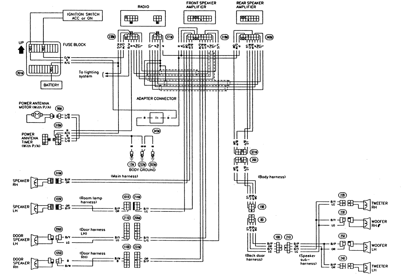
So, you're diving into the audio system of your 2009 Nissan Altima, huh? Whether you're upgrading the head unit, diagnosing a faulty speaker, or simply curious about how it all connects, understanding the radio wiring diagram is absolutely crucial. This isn't just about wires; it's about understanding the electrical language of your car's sound system. We'll break down the diagram, making sense of the symbols, colors, and connections so you can tackle your audio project with confidence. And, good news, we have the complete wiring diagram file for the 2009 Nissan Altima that you can download to reference as we go.
Purpose of the Wiring Diagram
Why bother with a wiring diagram? Several key reasons:
- Repairing Faulty Wiring: If a speaker isn't working, or your head unit suddenly shuts off, the diagram helps you trace the circuit and pinpoint the break or short.
- Upgrading Your Audio System: Installing a new head unit, amplifier, or speakers requires you to understand the existing wiring to properly integrate the new components.
- Adding Aftermarket Accessories: Integrating things like a subwoofer, Bluetooth adapter, or backup camera often involves tapping into existing wiring, which you can do safely and correctly with the diagram.
- Learning: Even if you're not currently working on your car, understanding the diagram provides valuable insight into automotive electrical systems.
Key Specs and Main Parts in the 2009 Altima Audio System
Let's outline the main components and some common specifications you'll encounter in the 2009 Altima's audio system.
- Head Unit (Radio): This is the central control unit. The 2009 Altima came with various head unit options, from basic AM/FM/CD players to models with navigation and satellite radio. The diagram will detail the pinout for the head unit connectors.
- Speakers: Typically, the Altima has speakers in the front doors, rear deck, and sometimes tweeters in the A-pillars. The diagram will show the wiring for each speaker, including polarity (+ and -). Standard speaker impedance is often 4 ohms, but always verify for your specific model.
- Amplifier (if equipped): Some Altima models, particularly those with the premium Bose sound system, have a separate amplifier. The diagram will show the amplifier's location, input/output wiring, and power source.
- Antenna: The antenna receives radio signals. Its wiring is generally straightforward, but it's important to ensure it's properly connected for optimal reception.
- Wiring Harnesses: These are bundles of wires connecting the various components. The diagram will show the color coding and connections within the harnesses.
- Fuses: Fuses protect the system from overloads. The diagram might not explicitly show all fuse locations, but it's often associated with the power circuits depicted.
Understanding Wiring Diagram Symbols
Wiring diagrams use a standardized set of symbols to represent electrical components and connections. Deciphering these symbols is key to understanding the diagram. Let's look at the common ones you'll encounter in the 2009 Altima radio wiring diagram.
Lines
Lines represent wires.
- Solid Line: A continuous wire connecting two components.
- Dashed Line: Often represents a shielded wire or a ground connection.
- Line Crossing: If two lines cross without a dot, it means they are not connected.
- Line Crossing with a Dot: This indicates a junction or connection point where the wires are spliced together.
Colors
Each wire is assigned a specific color code. These codes are usually abbreviated (e.g., BLU for Blue, RED for Red, GRN for Green, YEL for Yellow, WHT for White, BLK for Black). The diagram key will list the color codes used.
Component Symbols
These symbols represent the actual electrical components. Here are some common ones:
- Resistor: A zigzag line.
- Capacitor: Two parallel lines.
- Coil/Inductor: A coiled line.
- Ground: Often represented by a series of decreasing horizontal lines or a triangle pointing downwards. Proper grounding is vital for a stable audio system.
- Fuse: A squiggly line inside a rectangle or a simple rectangle with a line through it.
- Speaker: A circle with a line bisecting it, sometimes with a "+" and "-" symbol indicating polarity.
- Diode: A triangle pointing to a vertical line.
- Transistor: Can have multiple variations, but will typically have three leads.
Connector Symbols
Connectors are represented by blocks or shapes with lines pointing to the wires. The diagram will usually label the connector with a code (e.g., M12, B25) and indicate the pin numbers within the connector.
How It Works: Tracing the Audio Signal
Understanding how the audio signal flows through the system is crucial for troubleshooting. Typically, the signal originates from the head unit. Here's a simplified breakdown:
- Signal Origin: The head unit generates the audio signal (e.g., from the radio, CD player, or auxiliary input).
- Signal Processing (if applicable): The signal may pass through an internal amplifier in the head unit or an external amplifier. The amplifier boosts the signal's power.
- Signal Distribution: The amplified signal is sent to the speakers through the wiring harness. The diagram will show which wires connect to each speaker.
- Grounding: Each component, especially the head unit and amplifier, requires a proper ground connection. A bad ground can cause a variety of issues, including hum, distortion, and complete system failure. Verify the ground connections are secure and free of corrosion.
Real-World Use: Basic Troubleshooting Tips
Here's how you can use the wiring diagram to troubleshoot common audio problems:
- No Sound from a Speaker: Use the diagram to trace the wiring from the head unit (or amplifier) to the speaker. Check for breaks, shorts, or loose connections. Use a multimeter to test the continuity of the wires. Also, check the speaker itself with a multimeter set to ohms. A reading of infinity (open circuit) usually indicates a blown speaker.
- Head Unit Not Powering On: Check the power and ground connections to the head unit. Verify the fuse is not blown. Use a multimeter to check for voltage at the power wire with the ignition on.
- Humming or Static: This often indicates a grounding issue. Check the ground connections for all components, especially the head unit and amplifier.
- Distorted Sound: Can be caused by a blown speaker, a faulty amplifier, or incorrect wiring. Use the diagram to verify the wiring and test the components.
Safety Precautions
Working with automotive electrical systems can be dangerous. Here are some crucial safety precautions:
- Disconnect the Battery: Always disconnect the negative terminal of the battery before working on the electrical system. This prevents accidental shorts and potential electrical shocks.
- Use Proper Tools: Use insulated tools to prevent shorts.
- Be Aware of Airbag Wiring: Airbag circuits are often located near audio system wiring. Avoid disturbing these circuits, as accidental deployment can cause serious injury. The wiring diagram will usually indicate the location of airbag-related wiring.
- Double-Check Your Work: Before reconnecting the battery, carefully review your wiring to ensure everything is connected correctly.
Remember, if you're unsure about any aspect of the wiring, it's best to consult a qualified automotive electrician. Don't risk damaging your car or injuring yourself.
We mentioned earlier that we have the complete 2009 Nissan Altima radio wiring diagram file available. You can download it to have a handy reference while you work. It's much easier to trace wires and identify components with the full diagram in front of you!