
2009 Nissan Altima Stereo Wiring Diagram
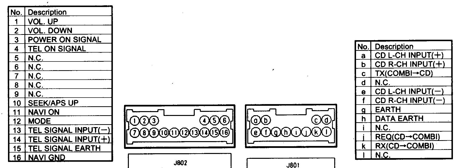
So, you're diving into the stereo wiring of your 2009 Nissan Altima, huh? Whether you're upgrading your head unit, troubleshooting a faulty speaker, or just curious about how it all connects, understanding the wiring diagram is crucial. This guide will break down the 2009 Altima stereo wiring diagram, making it accessible for even the most experienced DIY enthusiast. We'll cover the key specs, explain the symbols, and provide some real-world troubleshooting tips to help you get the job done safely and effectively.
Purpose of the 2009 Nissan Altima Stereo Wiring Diagram
Why bother with a wiring diagram? Several reasons. First, it's your roadmap for any modification or repair you're planning. Swapping out the factory head unit for a modern aftermarket one? You'll need to know which wire is power, ground, accessory, and each speaker lead. Second, troubleshooting electrical problems becomes significantly easier. A blown fuse, a dead speaker, or a mysterious short – the diagram helps you trace the circuit and pinpoint the issue. Finally, understanding the wiring allows you to make custom modifications safely, like adding an amplifier or subwoofer. Bypassing the factory amp, for example, requires a solid understanding of the pinouts, and the wiring diagram is your key.
Key Specs and Main Parts of the Stereo System
Before we delve into the diagram itself, let's look at the main components of the 2009 Altima's stereo system. Knowing where these parts are located and how they interact is crucial.
- Head Unit: The brains of the operation, also known as the radio or receiver. It processes audio signals from various sources (AM/FM radio, CD player, AUX input, potentially Bluetooth in some models) and sends them to the speakers, either directly or through an amplifier.
- Speakers: The physical drivers that convert electrical signals into sound waves. The 2009 Altima typically has four speakers (two front, two rear), though some models might have additional tweeters or a subwoofer.
- Amplifier (if equipped): Some Altima models feature a factory-installed amplifier. This amplifies the audio signal from the head unit, providing more power to the speakers for a louder, cleaner sound. Location varies but is commonly found under the passenger seat or in the trunk.
- Wiring Harnesses: These are the connectors that plug into the back of the head unit and other components, carrying the electrical signals. Understanding these connections is key.
- Antenna: Responsible for receiving radio signals.
- Fuses: Protect the electrical circuits from overloads. Blown fuses are a common cause of stereo problems, and knowing which fuse controls the stereo system is important.
The 2009 Altima's factory stereo typically operates on a 12-volt DC system, standard for automotive applications. Speaker impedance is generally 4 ohms.
Decoding the Symbols: Wires, Colors, and Icons
The wiring diagram is a schematic representation of the electrical system. To understand it, you need to be familiar with the symbols and conventions used:
- Lines: Represent wires. A thicker line might indicate a wire with a higher current carrying capacity.
- Colors: Wires are color-coded for identification. The diagram will have a legend that explains what each color represents. Common colors include:
- Red: Typically indicates a constant power source (12V+).
- Yellow: Usually indicates an accessory power source (switched 12V+), meaning it's only on when the ignition is on.
- Black: Ground (0V).
- White: Often used for speaker wires, along with gray, green, and violet. These will usually be paired with a same-color wire that is either striped or has a different gauge to identify the positive and negative leads.
- Icons: Represent components like the head unit, speakers, fuses, and connectors. These icons are generally standardized but may vary slightly depending on the diagram's source. Look for a key or legend on the diagram that defines each symbol.
- Numbers/Letters: Refer to the specific pin numbers on connectors. This is critical when connecting aftermarket components or troubleshooting wiring issues. You'll often see connector pinouts listed, showing which wire color corresponds to which pin number on the connector.
Pay close attention to the polarity (positive and negative) of the speaker wires. Reversing the polarity can cause the speakers to be out of phase, resulting in poor sound quality, specifically a loss of bass response. Wiring diagrams will usually mark positive and negative leads (+ and -).
How It Works: Tracing the Signal Path
The stereo system works by taking an audio signal, amplifying it, and sending it to the speakers. The wiring diagram illustrates this process. Here's a simplified breakdown:
- Power Source: The system receives power from the car's battery, typically through a fuse. The constant 12V (usually red wire) keeps the head unit's memory alive (for presets, etc.). The accessory 12V (usually yellow wire) turns the head unit on and off with the ignition. The ground (usually black wire) provides the return path for the current.
- Signal Input: The head unit receives audio signals from various sources (radio antenna, CD player, AUX input, Bluetooth).
- Signal Processing: The head unit processes the audio signal, adjusting volume, tone, and balance.
- Amplification: The head unit amplifies the signal (or sends it to an external amplifier).
- Speaker Output: The amplified signal is sent to the speakers through speaker wires.
- Sound Production: The speakers convert the electrical signal into sound waves.
The wiring diagram shows the path of each wire, from the power source to the speakers. You can trace the signal path to understand how each component interacts with the others. This is invaluable for troubleshooting.
Real-World Use: Basic Troubleshooting Tips
Armed with the wiring diagram, you can tackle common stereo problems:
- No Power: Check the fuses first. The wiring diagram will tell you which fuse controls the stereo. If the fuse is blown, replace it with a fuse of the same amperage. If the fuse blows again immediately, there's a short circuit somewhere in the wiring. Use the wiring diagram to trace the power wire and look for damaged insulation or exposed wires that could be grounding out.
- No Sound from One Speaker: First, check the speaker wiring. Ensure the connections are secure and the wires are not damaged. Use the wiring diagram to trace the speaker wires back to the head unit or amplifier. If the wiring is good, the speaker itself might be blown. You can test the speaker's continuity with a multimeter. If there is no continuity (an open circuit), the speaker is likely bad.
- Distorted Sound: Distorted sound can be caused by several factors, including blown speakers, loose wiring connections, or a faulty amplifier. Check the wiring connections and test the speakers. If the problem persists, the amplifier might be the culprit.
- Head Unit Won't Turn On: Use the wiring diagram to verify that the head unit is receiving both constant and switched power. Check the ground connection as well. A poor ground can cause all sorts of electrical problems.
Important Tip: Always disconnect the negative terminal of the battery before working on any electrical component in your car. This prevents accidental shorts and potential damage to the electrical system. Also, use a multimeter to verify voltages and continuity before making any connections. A multimeter is your best friend when troubleshooting electrical issues.
Safety: Highlighting Risky Components
Working with car electrical systems can be dangerous if you're not careful. Here are some key safety considerations:
- Airbag Systems: The Altima stereo system is often located near airbag modules. Never disconnect or tamper with airbag wiring unless you are a qualified technician. Accidental deployment of an airbag can cause serious injury.
- Electrical Shorts: As mentioned, disconnect the battery before working on the system to avoid shorts. Shorts can damage components, blow fuses, and even start a fire.
- Proper Grounding: Ensure all components are properly grounded. A poor ground can cause electrical noise, distorted sound, and even damage to components.
- Wire Gauge: Use wires of the correct gauge (thickness) for the current they will be carrying. Undersized wires can overheat and cause a fire. Refer to the wiring diagram for recommendations, especially when adding aftermarket amplifiers.
- Read the Diagram Carefully: This seems obvious, but carefully study the wiring diagram before starting any work. Misinterpreting the diagram can lead to incorrect wiring and potential damage.
Working with car electrical systems can be challenging, but with patience, the right tools, and a good understanding of the wiring diagram, you can successfully upgrade or repair your 2009 Nissan Altima's stereo system.
You can download the full wiring diagram for the 2009 Nissan Altima stereo system from [insert download link here - hypothetical link to a PDF or image file]. Having the full diagram at your fingertips will be invaluable as you work on your project. Good luck!