2009 Nissan Maxima Alternator Wiring Diagram
Let's dive into the alternator wiring diagram for a 2009 Nissan Maxima. Understanding this diagram is crucial whether you're tackling a charging system issue, upgrading your electrical system, or simply expanding your automotive knowledge. Think of this as a roadmap to the heart of your Maxima's power generation. We're going to break it down in a way that's approachable, even if you're not a professional mechanic, but still technically sound enough to be useful for complex diagnostics.
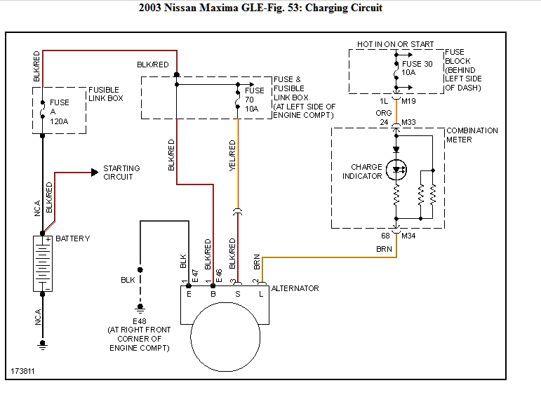
Purpose of the Alternator Wiring Diagram
Why bother understanding this diagram? Here's why:
- Troubleshooting Charging Problems: A dead battery or flickering lights are often alternator-related. The wiring diagram helps you pinpoint broken wires, faulty connections, or component failures within the charging circuit.
- Component Replacement: Replacing the alternator, battery, or even a fuse requires knowing how these components interact. The diagram shows you precisely which wires connect where.
- System Upgrades: Installing aftermarket accessories like a high-powered sound system or auxiliary lighting requires tapping into the electrical system. The wiring diagram is your guide to safely and effectively doing so.
- Understanding Your Car: Even if you're not currently having problems, understanding the electrical system helps you appreciate how your Maxima operates and potentially catch problems before they become major headaches.
Key Specs and Main Parts of the 2009 Maxima Alternator Circuit
Before we dive into the diagram itself, let's review the key components and their basic function:
- Alternator: The heart of the charging system. It converts mechanical energy from the engine into electrical energy to charge the battery and power the vehicle's electrical systems. It contains a stator (stationary coils where electricity is generated), a rotor (rotating electromagnet), a rectifier (converts AC to DC), and a voltage regulator.
- Battery: Stores electrical energy and provides power to start the engine and operate electrical systems when the engine is off or the alternator's output is insufficient.
- Voltage Regulator: Maintains a constant voltage output from the alternator (typically around 13.8-14.4 volts) to prevent overcharging the battery and damaging electrical components. It's often integrated *into* the alternator itself on modern vehicles like the 2009 Maxima.
- Ignition Switch: Controls power to various circuits, including the alternator's exciter circuit.
- Fuses and Fusible Links: Protect the electrical system from overcurrent conditions. These are *critical* safety devices.
- Wiring Harness: A bundle of wires that connects the various components of the electrical system.
- Engine Control Module (ECM): The car's computer. The ECM may monitor alternator performance and adjust engine parameters accordingly.
Understanding Wiring Diagram Symbols
Wiring diagrams use standardized symbols to represent electrical components and connections. Here's a breakdown of common symbols you'll encounter in the 2009 Maxima alternator wiring diagram:
- Solid Lines: Represent wires. Thicker lines may indicate wires with a higher current-carrying capacity.
- Dashed Lines: Often indicate shielded wires or wires that are part of a larger harness.
- Circles: Typically represent connection points or terminals.
- Rectangles: Often represent components like relays, switches, or control modules.
- Resistor Symbol (zigzag line): Represents a resistor, which limits current flow.
- Ground Symbol (series of decreasing lines): Indicates a connection to the vehicle's chassis ground. A good ground is *essential* for proper electrical function.
- Fuse Symbol: A squiggly line inside a rectangle, representing a fuse.
- Diode Symbol: A triangle pointing to a line, indicating a diode (allows current flow in only one direction).
- Color Codes: Wires are color-coded for identification. You'll see abbreviations like:
- B: Black
- R: Red
- W: White
- G: Green
- L: Blue
- Y: Yellow
The diagram will also show wire gauge (thickness), usually represented by AWG (American Wire Gauge). Lower AWG numbers indicate thicker wires, capable of handling more current.
How the 2009 Maxima Alternator Circuit Works
Here's a simplified explanation of how the charging system operates:
- Starting the Engine: When you turn the ignition key, power is supplied to the starter motor, cranking the engine. Power is also supplied to the alternator's exciter circuit (also called the "ignition" or "sense" wire).
- Excitation: The exciter circuit provides a small amount of current to the alternator's rotor windings. This creates a magnetic field.
- Generating Electricity: As the engine runs, the alternator's rotor spins within the stator windings. This rotating magnetic field induces an alternating current (AC) in the stator windings.
- Rectification: The alternator's internal rectifier converts the AC current to direct current (DC).
- Voltage Regulation: The voltage regulator monitors the battery voltage and adjusts the current flowing through the rotor windings to maintain a stable output voltage (around 14 volts). If the battery voltage is low, the regulator increases the rotor current, increasing the alternator's output. If the battery voltage is high, the regulator decreases the rotor current, reducing the alternator's output.
- Charging the Battery: The DC current from the alternator is fed to the battery, charging it and replenishing the energy used during starting.
- Powering Electrical Systems: The alternator also provides power to operate all the vehicle's electrical systems, such as the headlights, radio, and climate control.
Real-World Use: Basic Troubleshooting Tips
Here are some common problems and how the wiring diagram can help you diagnose them:
- Battery Not Charging: Check the alternator's output voltage with a multimeter. If it's significantly below 13.8 volts, the alternator may be faulty. Use the wiring diagram to check the B+ (battery positive) terminal on the alternator for proper voltage and a good connection. Also, check the exciter wire for voltage with the ignition on.
- Overcharging: If the battery is constantly boiling or electrical components are failing prematurely, the voltage regulator may be faulty. Again, use a multimeter to check the alternator's output voltage. If it's significantly above 14.4 volts, the regulator is likely the problem.
- Battery Light On: This indicates a problem with the charging system. The wiring diagram can help you trace the circuit from the alternator to the instrument cluster to identify any broken wires or faulty sensors. It's also good to check the condition of the alternator belt.
- Parasitic Drain: If your battery keeps dying overnight, there may be a parasitic drain (something drawing power when the car is off). The wiring diagram can help you isolate the circuit causing the drain by systematically disconnecting fuses and measuring the current draw.
Safety Precautions
Working with automotive electrical systems can be dangerous. Here are some crucial safety tips:
- Disconnect the Battery: Always disconnect the negative battery cable before working on the electrical system. This prevents accidental shorts and electrical shocks.
- Use Proper Tools: Use insulated tools to avoid electrical shocks.
- Never Work on a Live Circuit: Unless specifically instructed to do so for diagnostic purposes, never work on a live circuit.
- Be Careful with the Airbag System: The airbag system is electrically controlled. Improper handling can cause accidental deployment, which can be dangerous. Refer to the service manual for specific instructions on disabling the airbag system before working near it.
- Identify High-Current Circuits: The alternator's B+ terminal is a high-current circuit. Be extremely careful when working near it. Accidental shorts can cause fires or serious burns.
Remember that a 2009 Nissan Maxima alternator outputs substantial current. Always disconnect the negative terminal of the battery before working on any part of the electrical system.
By understanding the 2009 Nissan Maxima alternator wiring diagram, you can confidently troubleshoot charging system problems, perform component replacements, and upgrade your vehicle's electrical system safely and effectively.
We have the complete, high-resolution 2009 Nissan Maxima alternator wiring diagram file available for you to download. This detailed diagram will be invaluable for your diagnostic and repair work.