2009 Nissan Sentra Fuse Box Diagram
Understanding your vehicle's fuse box is essential for performing basic maintenance, troubleshooting electrical problems, or even adding aftermarket accessories. For 2009 Nissan Sentra owners, this detailed guide to the fuse box diagram will provide a solid foundation for navigating its electrical system. Knowing the location and function of each fuse and relay empowers you to diagnose and fix common issues without needing to immediately consult a mechanic.
Purpose of the Fuse Box Diagram
The fuse box diagram is your roadmap to the Sentra's electrical system. It serves several crucial purposes:
- Troubleshooting Electrical Faults: When an electrical component malfunctions (e.g., a blown headlight, a non-functional radio), the fuse box is often the first place to check. The diagram allows you to quickly identify the fuse associated with that component.
- Performing Basic Maintenance: Before working on any electrical component, it's a good practice to disconnect the corresponding fuse to prevent accidental shorts or electrical shock. The diagram helps you locate the correct fuse for safe disconnection.
- Adding Aftermarket Accessories: If you're installing accessories like a new stereo system, auxiliary lights, or a dashcam, you'll likely need to tap into the car's electrical system. The diagram helps you identify suitable fuses for powering these accessories safely and without overloading circuits.
- Understanding the Electrical System: Studying the fuse box diagram provides a deeper understanding of how the different electrical systems in your Sentra are interconnected. This knowledge can be invaluable for more complex repairs or modifications.
Key Specs and Main Parts
The 2009 Nissan Sentra typically has two fuse box locations:
- Interior Fuse Box: Located inside the cabin, usually on the driver's side, often behind a small access panel on the lower part of the dashboard. This box primarily houses fuses for interior components like the radio, lights, power windows, and climate control system.
- Engine Compartment Fuse Box: Located under the hood, typically near the battery or on the fender well. This box contains fuses and relays for critical engine components such as the fuel pump, ignition system, and cooling fan.
Key Components Within the Fuse Boxes:
- Fuses: These are sacrificial devices designed to protect electrical circuits from overcurrent. They consist of a thin wire that melts and breaks the circuit if the current exceeds a safe level. Fuses are rated in amperes (amps, A), indicating the maximum current they can handle. Common ratings include 5A, 7.5A, 10A, 15A, 20A, 25A, and 30A.
- Relays: These are electrically operated switches that allow a low-current circuit to control a high-current circuit. They are used to control components that require a significant amount of power, such as headlights, starter motors, and air conditioning compressors.
- Circuit Breakers: Unlike fuses that need replacement after blowing, circuit breakers are reusable. They trip and break the circuit when an overload occurs, and can be reset once the issue is resolved. While less common than fuses in these fuse boxes, understanding their function is helpful.
- Fuse Puller: A small plastic tool used to safely remove fuses from the fuse box without damaging them.
Symbols, Lines, Colors, and Icons
Understanding the symbols and conventions used in the fuse box diagram is crucial for accurate interpretation:
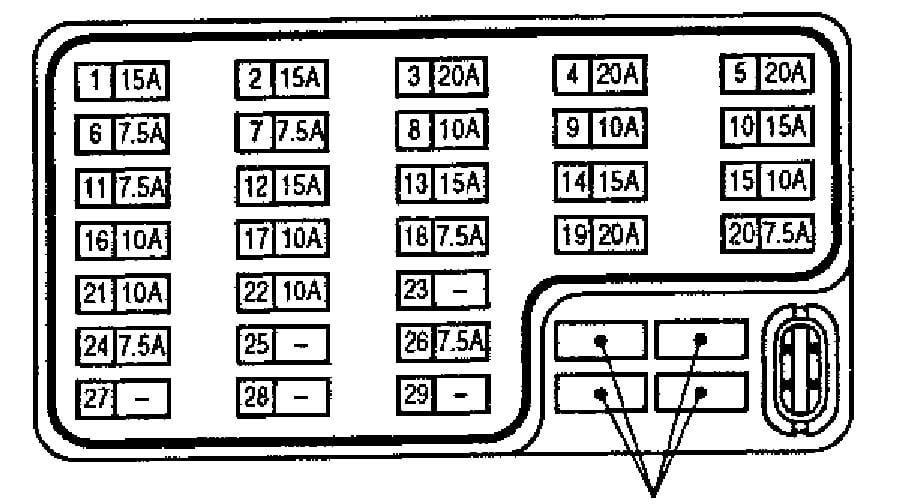
- Fuse Symbols: Fuses are typically represented by a zigzag line enclosed in a rectangular or oval shape. The amperage rating is usually indicated next to the symbol.
- Relay Symbols: Relays are often depicted as a coil with associated switch contacts. The diagram shows which circuits are controlled by each relay.
- Lines: Solid lines represent electrical wiring connections. Dashed lines may indicate ground connections.
- Colors: While not always present on all diagrams, color coding may be used to differentiate between different types of circuits or functions. Refer to the legend of your specific diagram if color coding is used.
- Icons/Labels: Each fuse and relay is typically labeled with an abbreviation or icon indicating the component or system it protects (e.g., "HEAD LP" for headlights, "RADIO" for radio, "A/C" for air conditioning). These labels are critical for correct identification.
How It Works
The fuse box serves as a central distribution point for electrical power throughout the vehicle. Power from the battery flows through the main fuses and then is distributed to various circuits via individual fuses and relays. When an electrical fault occurs, such as a short circuit, the excessive current flow causes the corresponding fuse to blow, interrupting the circuit and preventing damage to the wiring and components.
Relays, on the other hand, act as intermediaries, allowing low-current signals from switches or the vehicle's computer to control high-current circuits. For example, when you turn on your headlights, the switch in the cabin sends a low-current signal to the headlight relay, which then closes the high-current circuit powering the headlights.
Real-World Use – Basic Troubleshooting Tips
Here's a basic troubleshooting scenario:
- Symptom: Your car radio is not working.
- Step 1: Consult the fuse box diagram for the interior fuse box. Locate the fuse labeled "RADIO" or "AUDIO."
- Step 2: Use the fuse puller to carefully remove the identified fuse.
- Step 3: Inspect the fuse. If the wire inside the fuse is broken or melted, the fuse is blown.
- Step 4: Replace the blown fuse with a new fuse of the same amperage rating. Never use a fuse with a higher amperage rating, as this could overload the circuit and cause a fire.
- Step 5: Test the radio. If the radio works after replacing the fuse, the problem is solved. If the fuse blows again immediately, there is likely a short circuit in the radio wiring or the radio itself. This requires further investigation.
Important Notes:
- Always use the correct amperage rating fuse.
- If a fuse blows repeatedly, there's an underlying problem that needs to be addressed. Don't just keep replacing the fuse without investigating the cause.
- If you are unsure about any aspect of the electrical system, consult a qualified mechanic.
Safety – Highlight Risky Components
Working with the electrical system can be dangerous if proper precautions are not taken.
- Battery: The battery contains sulfuric acid, which can cause severe burns. Avoid contact with skin and eyes.
- High-Voltage Components: Be extremely careful when working near components such as the ignition coil or the alternator, as these can generate high voltages that can be fatal.
- Airbags: The airbag system is sensitive and can be accidentally deployed if handled improperly. Never tamper with the airbag wiring or components without proper training and precautions. Disconnect the battery and wait at least 10 minutes before working near airbags.
- General Precautions: Always disconnect the negative battery terminal before working on the electrical system. This will help prevent accidental shorts and electrical shock. Use insulated tools and wear appropriate safety gear, such as gloves and eye protection.
We have a readily accessible 2009 Nissan Sentra fuse box diagram file available for download to supplement this guide. You can use it as a reference when working on your car's electrical system. It contains more specific information about each fuse and relay location, as well as circuit details that are helpful for advanced diagnostics.