2009 Nissan Versa Fuse Box Diagram
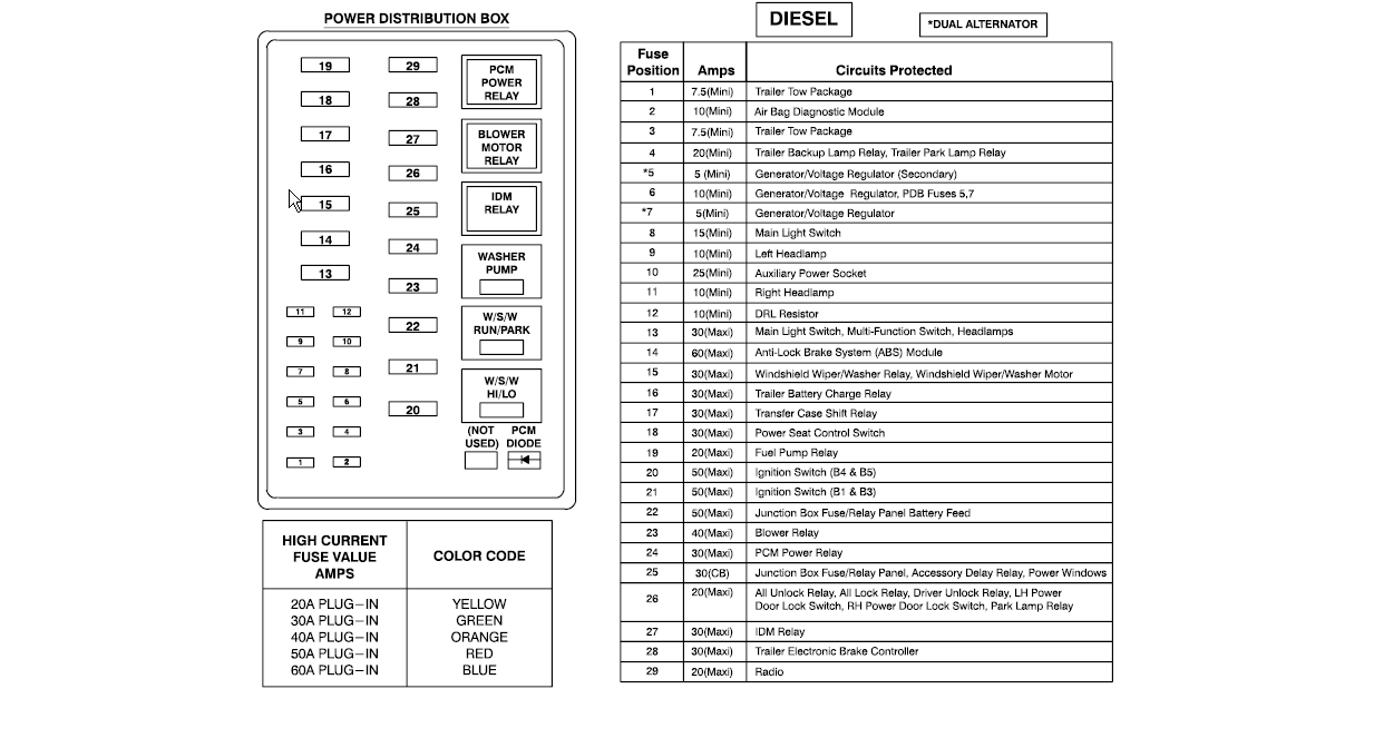
Let's dive into the fuse box diagram of a 2009 Nissan Versa. Understanding this diagram is crucial for a variety of reasons. Whether you're troubleshooting electrical issues, planning modifications, or just want a deeper understanding of your vehicle, knowing your way around the fuse box can save you time, money, and potentially prevent further damage. This guide will provide a detailed breakdown, assuming a level of familiarity with automotive systems.
Purpose of the Fuse Box Diagram
The fuse box diagram serves as a roadmap for your car's electrical system. Its primary purpose is to identify the location and function of each fuse and relay within the fuse boxes. This is invaluable for:
- Troubleshooting Electrical Problems: When a circuit malfunctions (e.g., a headlight stops working), the fuse box diagram helps you quickly locate the corresponding fuse and determine if it's blown.
- Performing Repairs: Knowing which fuse controls which component allows you to isolate problems and prevent cascading failures during repairs.
- Planning Modifications: If you're adding aftermarket accessories like amplifiers or lights, the diagram assists in identifying suitable power sources and proper fusing to protect the new circuits and the existing electrical system.
- General Understanding: Even without immediate problems, understanding the diagram provides insight into how different components of your car are electrically interconnected.
Key Specs and Main Parts
The 2009 Nissan Versa typically has two main fuse boxes:
- Interior Fuse Box: Located inside the cabin, often under the dashboard on the driver's side or behind a small access panel. This box houses fuses for interior lights, power windows, radio, climate control, and other comfort/convenience features.
- Engine Compartment Fuse Box: Found under the hood, usually near the battery. This box contains fuses and relays for vital engine components like the fuel pump, ignition system, engine control unit (ECU), headlights, and other critical systems.
Within each fuse box, you'll find:
- Fuses: These are safety devices designed to protect electrical circuits from overcurrent. They contain a thin wire that melts and breaks the circuit when excessive current flows through it. Fuses are rated in amperes (amps or A), indicating the amount of current they can handle before blowing. Common ratings include 5A, 7.5A, 10A, 15A, 20A, 25A, 30A, and higher.
- Relays: Electrically operated switches used to control high-current circuits with a low-current signal. They allow a small current to switch on a larger current, which is crucial for components like the starter motor, fuel pump, and headlights. A typical relay includes a coil, contacts (normally open or normally closed), and a common terminal.
- Fuse Puller: A small plastic tool, often integrated into the fuse box cover, used to safely remove and replace fuses.
- Fuse Box Cover: This cover usually has a diagram printed on it or attached to its underside, indicating the function and amperage rating of each fuse and relay.
Symbols – Lines, Colors, and Icons
Fuse box diagrams use various symbols to represent different components and their connections. Here's a breakdown of common symbols:
- Fuses: Typically represented by a simple rectangle or a symbol resembling a wavy line. The amperage rating is usually printed next to the symbol.
- Relays: Often depicted as a square or rectangle with internal lines indicating the coil and contacts. The function of the relay might be labeled near the symbol (e.g., "Fuel Pump Relay").
- Lines: Solid lines represent electrical wiring, while dashed lines might indicate ground connections or control signals.
- Colors: While the diagram itself is often black and white, the actual wires in the car are color-coded. A separate wiring diagram, which is different from the fuse box diagram, will show the color coding for the wires connecting the various electrical components.
- Icons: Small icons might be used to represent specific components, such as a headlight bulb icon for the headlight fuse or a steering wheel icon for the power steering fuse.
Important Note: Always refer to the specific diagram for your 2009 Nissan Versa model and trim level, as slight variations can exist. The diagram on the fuse box cover is generally the most accurate resource.
How It Works
The fuse box acts as a central distribution point for electrical power. Power from the battery flows through the fuse box, and then each individual circuit is protected by a fuse. If a short circuit or overload occurs in a particular circuit, the fuse for that circuit blows, interrupting the flow of electricity and preventing damage to the wiring and components connected to that circuit.
Relays, on the other hand, are used to control high-current circuits with low-current signals. For example, the starter motor requires a large amount of current to operate. Instead of running thick wires from the ignition switch to the starter motor, a relay is used. The ignition switch sends a low-current signal to the relay, which then closes the circuit, allowing the high current from the battery to flow to the starter motor.
Real-World Use – Basic Troubleshooting Tips
Here's a basic troubleshooting scenario:
- Symptom: The radio is not working.
- Diagnosis: Consult the fuse box diagram (either on the cover or downloaded). Locate the fuse labeled "Radio" or "Audio System."
- Inspection: Use the fuse puller to remove the fuse. Visually inspect the fuse. If the thin wire inside the fuse is broken or blackened, the fuse is blown.
- Replacement: Replace the blown fuse with a new fuse of the exact same amperage rating. Never use a fuse with a higher amperage rating, as this could damage the wiring and components.
- Test: Turn on the radio to see if it now works.
- If the Problem Persists: If the new fuse blows immediately or the radio still doesn't work, there's likely a more serious underlying problem, such as a short circuit in the wiring or a faulty radio. Further diagnostics are needed.
Safety – Highlight Risky Components
Working with automotive electrical systems can be dangerous. Here are some crucial safety precautions:
- Disconnect the Battery: Before working on any electrical components, disconnect the negative (-) terminal of the battery to prevent accidental short circuits and electric shock.
- Use the Correct Fuses: Always replace blown fuses with fuses of the same amperage rating. Using a higher amperage fuse can bypass the circuit protection and lead to serious damage or fire.
- Avoid Working on Wet Surfaces: Water is a conductor of electricity. Never work on electrical systems in wet conditions.
- Be Cautious Around High-Current Components: Components like the starter motor, alternator, and battery cables carry high currents. Avoid touching these components while the engine is running or the ignition is on.
- Don't Probe Live Wires: Avoid probing or testing live wires unless you have experience and the proper equipment.
- Consult a Professional: If you are not comfortable working with electrical systems, consult a qualified mechanic. Electrical problems can be complex and dangerous to diagnose and repair.
- Airbags: Be extremely careful when working near airbag control modules and wiring. Accidental deployment of an airbag can cause serious injury. Refer to the service manual for specific instructions on disabling the airbag system before working in these areas.
By understanding the 2009 Nissan Versa fuse box diagram and following proper safety precautions, you can confidently troubleshoot electrical problems and maintain your vehicle's electrical system. The diagrams are invaluable tools. They provide a quick reference for identifying fuse functions and troubleshooting issues, ultimately saving you time and money.
We have the 2009 Nissan Versa fuse box diagram file; you can download it for a detailed view of your car electrical components.