2009 Silverado Radio Wiring Harness Diagram
Alright, let's dive into the wiring harness diagram for the 2009 Chevrolet Silverado radio. This isn't just some pretty picture; it's your roadmap when dealing with anything related to the audio system in your truck. Whether you're upgrading your head unit, troubleshooting a speaker issue, or adding an amplifier, understanding this diagram is crucial.
Purpose of the 2009 Silverado Radio Wiring Harness Diagram
Why bother with this diagram? Simple. It's your key to:
- Repairs: A blown fuse, a frayed wire – this diagram helps you pinpoint the exact location of the problem in the audio circuit.
- Upgrades: Swapping out the factory radio for a fancy aftermarket unit? You'll need to know which wires are power, ground, speakers, etc.
- Adding Accessories: Integrating an amplifier, subwoofer, or even just a hands-free Bluetooth kit requires tapping into the existing wiring, and this diagram ensures you do it safely and correctly.
- Learning: Even if you're not currently working on your radio, understanding the wiring helps you grasp the overall electrical system of your vehicle, which is invaluable for any DIY mechanic.
Key Specs and Main Parts of the Wiring Harness
The 2009 Silverado radio wiring harness is a complex system, but it boils down to several key components:
- Power Wires: These provide the necessary voltage (typically 12V DC) to power the radio and other audio components. There's usually a constant power wire (for memory retention) and a switched power wire (activated by the ignition).
- Ground Wires: Provides the return path for the electrical current. A good, clean ground connection is essential for proper operation.
- Speaker Wires: These carry the audio signal from the radio to the speakers. Each speaker (front left, front right, rear left, rear right) has a positive (+) and a negative (-) wire.
- Antenna Wire: Connects the radio to the vehicle's antenna, allowing you to receive radio signals. Often a coaxial cable.
- Data Wires (CAN Bus): Modern vehicles use a CAN (Controller Area Network) bus to communicate between various electronic modules. The radio often interfaces with the CAN bus for features like steering wheel controls, vehicle speed information, and diagnostics.
- Remote Turn-On Wire (Amplifier): If you're adding an aftermarket amplifier, this wire signals the amplifier to turn on when the radio is powered on.
Understanding these components is the first step in deciphering the wiring diagram. You'll see each of these represented by different colors, lines, and symbols.
Symbols, Lines, and Colors: Deciphering the Diagram
The diagram isn't just a jumble of lines; it uses a standardized system to represent different components and connections. Here’s a breakdown:
- Lines: Solid lines represent wires, while dashed lines might indicate a shielded cable or a connection to the CAN bus. Thicker lines often indicate wires carrying higher current (like power wires).
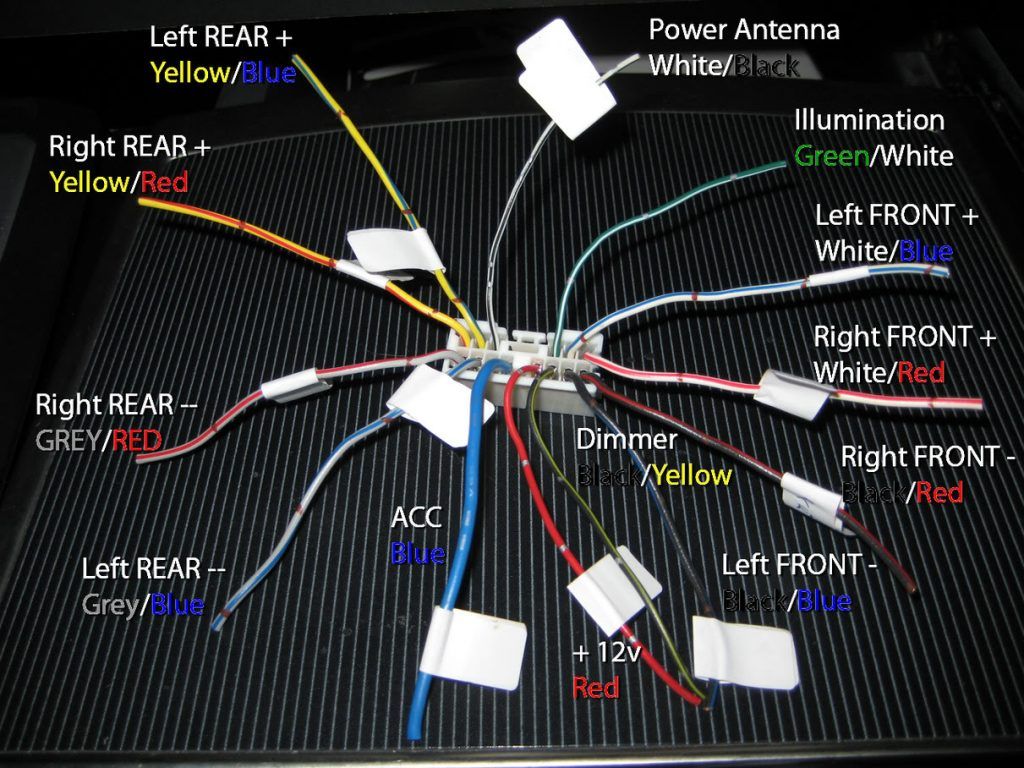
- Colors: Each wire is color-coded, and the diagram will have a legend indicating what each color represents. Common colors include red (power), black (ground), yellow (constant power), and various colors for speaker wires (e.g., white/blue, green/black). Always double-check the color code on the diagram itself as color codes can vary slightly depending on the trim level and specific options of the vehicle.
- Symbols: You'll see symbols representing various components, such as:
- Resistors: A zig-zag line.
- Capacitors: Two parallel lines.
- Fuses: A small rectangle with a line through it.
- Ground: A series of downward-pointing lines, usually getting smaller.
- Connectors: Represented by squares or circles, often with numbers indicating pin locations.
The key is to find the legend on the diagram. It's usually located at the bottom or side and provides a key to all the symbols and color codes used.
How It Works: Tracing the Circuit
Let's imagine you want to trace the circuit for the front left speaker. Here’s how you’d do it using the diagram:
- Locate the radio connector: Find the symbol representing the radio unit in the diagram.
- Identify the speaker wires: Look for the wires labeled "Front Left Speaker +" and "Front Left Speaker -". These wires will likely be a specific color combination, as indicated in the legend.
- Trace the wires: Follow the lines representing those wires from the radio connector. You'll see them pass through connectors, potentially through a factory amplifier (if equipped), and eventually to the speaker itself.
- Note any intermediate components: Along the way, note any resistors, capacitors, or other components in the circuit. These components can affect the audio signal and could be potential points of failure.
By tracing the circuit, you can understand how the audio signal flows from the radio to the speaker. This is invaluable for troubleshooting problems.
Real-World Use: Basic Troubleshooting Tips
Here are a few troubleshooting scenarios where the wiring diagram comes in handy:
- No Power to Radio: Use the diagram to trace the power wires (both constant and switched) back to the fuse box. Check the fuses to see if any are blown. Also, verify that the ground wire has a good connection to the chassis.
- Speaker Not Working: Trace the speaker wires from the radio to the speaker. Check for broken wires, loose connections at the speaker terminals, or a damaged speaker. Use a multimeter to check for continuity in the wiring.
- Steering Wheel Controls Not Working: These often rely on the CAN bus. Check the wiring connections to the radio and the CAN bus module. Make sure the radio is properly programmed to recognize the steering wheel controls.
- Excessive Noise: Noise can be caused by a poor ground connection. Use the diagram to identify all ground connections and ensure they are clean and secure. Also, check for any loose or damaged speaker wires, which can act as antennas and pick up interference.
Safety: Highlight Risky Components
Working with electrical systems can be dangerous. Always disconnect the negative terminal of the battery before working on the radio wiring. Be particularly cautious when working with:
- Airbag System: The airbag system has its own wiring and control modules. Tampering with this system can be extremely dangerous and could result in accidental airbag deployment. Avoid working near airbag components unless you are specifically trained to do so.
- Power Wires: Shorting a power wire to ground can cause a fire. Always use a multimeter to verify the voltage and polarity of wires before connecting anything to them.
- CAN Bus: Incorrectly tapping into the CAN bus can disrupt the communication between various electronic modules in the vehicle. Consult the diagram carefully and use proper techniques to avoid damaging the CAN bus system.
Always consult a qualified technician if you are unsure about any aspect of the wiring or are uncomfortable working on the electrical system.
Having a solid understanding of the 2009 Silverado radio wiring harness diagram empowers you to tackle audio-related projects with confidence and safety. Remember to take your time, double-check your work, and always prioritize safety.
We have a high-resolution, printable version of the 2009 Silverado Radio Wiring Harness Diagram available for you to download. This diagram provides clear and detailed information that will be invaluable for your projects. We have the file. If you are reading this article online, please find the link to download the diagram below the article. If you are reading this article in HTML format, please look for the diagram link. You can also copy and paste the content of this document into a word processor and save it as a PDF for offline access, then search for the diagram from search engine for a quicker solution.