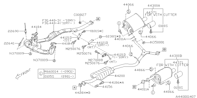
2009 Subaru Forester Exhaust System Diagram
The exhaust system of a 2009 Subaru Forester is a complex assembly of components designed to safely and efficiently remove combustion byproducts from the engine. Understanding the exhaust system is crucial for everything from basic maintenance to diagnosing performance issues or even planning modifications. This article provides a comprehensive overview of the 2009 Subaru Forester exhaust system diagram, equipping you with the knowledge to tackle repairs, upgrades, and troubleshooting with confidence.
Purpose of the Exhaust System Diagram
An exhaust system diagram serves multiple important purposes:
- Diagnostic Aid: It helps pinpoint the location of leaks, blockages, or failing components. A rattling sound? Check the diagram to see if a heat shield is loose. Poor fuel economy? The oxygen sensor locations can be identified.
- Repair Reference: It guides you through the correct order of disassembly and reassembly, ensuring proper sealing and component alignment. Knowing the torque specifications for each fastener is also vital, and often can be derived based on the fastener size shown in the diagram.
- Modification Planning: Whether you're considering a cat-back exhaust system or upgrading the header, the diagram provides a visual representation of the system's layout, facilitating a smooth and informed upgrade process.
- Learning Tool: Even if you're not planning immediate work, studying the diagram will deepen your understanding of how your vehicle functions.
Key Specs and Main Parts of the 2009 Subaru Forester Exhaust System
The 2009 Subaru Forester's exhaust system, in its stock configuration, generally consists of the following main parts:
- Exhaust Manifold (Header): The starting point of the system, bolting directly to the cylinder head(s). It collects exhaust gases from each cylinder. The 2009 Forester utilizes a 2-into-1 header design.
- Catalytic Converter(s): A crucial emission control device that uses a catalyst to convert harmful pollutants (hydrocarbons, carbon monoxide, and nitrogen oxides) into less harmful substances. The 2009 Forester utilizes multiple catalytic converters.
- Oxygen Sensors (O2 Sensors): These sensors monitor the oxygen content in the exhaust stream. There are typically two types: upstream sensors (before the catalytic converter) that help the engine control unit (ECU) adjust the air-fuel mixture, and downstream sensors (after the catalytic converter) that monitor the converter's efficiency.
- Resonator: A component designed to reduce specific frequencies of sound, helping to minimize unwanted noise and drone.
- Muffler: The final sound-dampening component in the system. It uses a series of chambers and passages to further reduce exhaust noise before it exits the tailpipe.
- Piping: Connects all the components together. The diameter and material of the piping significantly impact exhaust flow and performance. Typical material is mild steel, but stainless-steel is often used for aftermarket upgrades.
- Gaskets and Seals: Located at each joint to prevent exhaust leaks. They are crucial for maintaining proper exhaust pressure and preventing harmful gases from entering the cabin.
- Hangers and Mounts: Rubber or polyurethane mounts that support the exhaust system and isolate it from the vehicle's chassis, preventing vibrations and noise from transferring to the cabin.
Key Specs: While specific dimensions vary depending on the engine type (2.5L naturally aspirated or 2.5L turbocharged), the exhaust piping diameter is typically around 2-2.25 inches for the naturally aspirated models and slightly larger for the turbocharged models. Header configurations can also vary.
Understanding Symbols in the Exhaust System Diagram
Exhaust system diagrams use a variety of symbols to represent different components and connections. While specific diagram conventions might vary, here are some common symbols:
- Solid Lines: Typically represent exhaust piping. The thickness of the line might indicate the pipe diameter.
- Dashed Lines: Often represent vacuum lines associated with emission control systems or heat shields.
- Circles or Ovals: Often represent components like oxygen sensors, catalytic converters, or mufflers. These may have abbreviations inside (e.g., "CAT" for catalytic converter, "O2S" for oxygen sensor).
- Arrows: Indicate the direction of exhaust gas flow.
- Fastener Symbols: Bolts, nuts, and clamps are represented by small circles, squares, or other shapes, sometimes with torque specifications (e.g., "25 Nm").
- Color Coding: Some diagrams use color coding to differentiate between different materials or system sections. Check the diagram legend for specific color meanings.
How the Exhaust System Works
The exhaust system's primary function is to evacuate spent gases from the engine cylinders and safely vent them into the atmosphere. Here's a breakdown of the process:
- Exhaust Stroke: During the exhaust stroke of the engine cycle, the exhaust valve opens, and the piston pushes the burnt air-fuel mixture out of the cylinder.
- Exhaust Manifold Collection: The exhaust gases are collected by the exhaust manifold (or header), which channels them from each cylinder into a single or paired pipe(s).
- Catalytic Conversion: The gases pass through the catalytic converter(s), where harmful pollutants are converted into less harmful substances through chemical reactions.
- Oxygen Sensor Monitoring: Oxygen sensors monitor the oxygen content before and after the catalytic converter. The ECU uses this information to adjust the air-fuel mixture for optimal combustion and to monitor the catalytic converter's efficiency.
- Sound Dampening: The exhaust gases then flow through a resonator (if equipped) and a muffler, which reduce noise levels before being expelled from the tailpipe.
Real-World Use and Basic Troubleshooting Tips
Here are some common issues and how the exhaust system diagram can help:
- Exhaust Leaks: Use the diagram to locate potential leak points (gaskets, flanges, welds). Check for black soot around these areas. A leaking exhaust manifold gasket can cause a ticking sound, especially when the engine is cold.
- Rattling Noises: Check the diagram to identify heat shields and hangers. Loose or broken hangers or heat shields can cause rattling.
- Check Engine Light (CEL): If the CEL is on, use an OBD-II scanner to retrieve the diagnostic trouble code (DTC). Many codes relate to oxygen sensors or catalytic converter efficiency. The diagram will help you locate the affected sensor or converter.
- Reduced Performance: A clogged catalytic converter or a collapsed exhaust pipe can restrict exhaust flow, reducing engine power. Visually inspect the exhaust system for damage or blockages.
- Fuel Smell: A strong fuel smell could indicate a fuel leak near the exhaust system (very dangerous!) or a malfunctioning catalytic converter.
Safety Considerations
Working on the exhaust system can be dangerous due to high temperatures and potentially harmful gases:
- Cool Down: Always allow the exhaust system to cool down completely before working on it. Even after the engine is off, the exhaust system remains extremely hot for a considerable time.
- Ventilation: Work in a well-ventilated area to avoid inhaling exhaust fumes. Carbon monoxide is odorless and deadly.
- Eye Protection: Wear safety glasses to protect your eyes from debris and rust.
- Gloves: Wear gloves to protect your hands from burns, sharp edges, and chemicals.
- Support: When removing exhaust components, use jack stands to support the vehicle and prevent accidents. Never work under a vehicle supported only by a jack.
- Oxygen Sensor Safety: Oxygen sensors can be damaged if dropped or contaminated. Handle them with care.
- Catalytic Converter Warning: The catalytic converter reaches extremely high temperatures during operation. Avoid touching it even after the engine has been off for a while.
Understanding the exhaust system diagram and following safety precautions will allow you to confidently diagnose and address exhaust system issues on your 2009 Subaru Forester.
We have a detailed 2009 Subaru Forester Exhaust System Diagram available for download. This diagram provides a clear and comprehensive view of all the components and their locations, making it an invaluable resource for any repair or modification project.