2010 Chevy Traverse Serpentine Belt Diagram
The 2010 Chevy Traverse is a reliable family SUV, but like any vehicle, it requires regular maintenance. One crucial component is the serpentine belt, also known as the accessory drive belt. This article provides a detailed look at the 2010 Chevy Traverse serpentine belt diagram, offering insights for experienced DIYers, modders, and intermediate car owners who want to understand, maintain, or replace this critical part. We'll cover the diagram's purpose, key specs, component identification, how the system functions, real-world troubleshooting, safety precautions, and where to find the diagram for download.
Purpose of the Serpentine Belt Diagram
The serpentine belt diagram serves as a visual guide, illustrating the routing of the serpentine belt around various engine accessories. This routing is critical for proper operation. The diagram is invaluable for several reasons:
- Replacement: When replacing a worn or damaged serpentine belt, the diagram ensures correct installation. An incorrectly routed belt can lead to accessory failure and potential engine damage.
- Troubleshooting: The diagram aids in diagnosing accessory issues. If a particular accessory isn't functioning correctly, the diagram helps determine if the belt is properly engaged.
- Maintenance: Regular inspection of the belt and its alignment with the pulleys is crucial for preventative maintenance. The diagram provides a reference point for verifying correct alignment.
- Education: Understanding the serpentine belt system enhances your overall automotive knowledge. It allows you to grasp how different engine components interact and function together.
Key Specs and Main Parts
Before diving into the diagram itself, let's outline the key components and specifications related to the 2010 Chevy Traverse serpentine belt system.
Main Components:
- Serpentine Belt: A single, long belt made of reinforced rubber that drives multiple accessories. The specific length and rib configuration vary depending on the engine and model options, but the diagram assumes a factory specified belt.
- Crankshaft Pulley: Driven directly by the engine's crankshaft, this pulley provides the rotational force that powers the serpentine belt.
- Alternator Pulley: The alternator generates electrical power for the vehicle. The serpentine belt drives the alternator pulley.
- Power Steering Pump Pulley: Powers the hydraulic system for power-assisted steering. The serpentine belt drives this pulley.
- Air Conditioning (A/C) Compressor Pulley: The A/C compressor is responsible for cooling the vehicle's interior. It is powered by the serpentine belt.
- Water Pump Pulley: The water pump circulates coolant throughout the engine to prevent overheating. It is also driven by the serpentine belt.
- Tensioner Pulley: The tensioner pulley maintains proper tension on the serpentine belt. It usually has a spring-loaded mechanism to automatically adjust for belt wear and stretch.
- Idler Pulley(s): Some Traverse models may have one or more idler pulleys. These pulleys simply guide the belt and do not drive any accessories.
Key Specs:
Belt Length: The specific belt length is crucial and varies depending on engine options and whether or not the vehicle has A/C. Consult the parts catalog or the VIN decoder to determine the exact belt length for your specific Traverse.
Belt Material: Serpentine belts are typically made from EPDM (Ethylene Propylene Diene Monomer) rubber. Modern belts are designed for extended life and resistance to heat and cracking.
Symbols in the Diagram
Understanding the symbols used in the serpentine belt diagram is vital for accurate interpretation.
- Solid Lines: Represent the path of the serpentine belt. The line thickness might indicate the belt's width or simply emphasize its route.
- Dotted Lines: May indicate the "backside" of the belt coming into contact with a pulley (where the smooth side of the belt touches the pulley). This is especially important around idler pulleys.
- Arrows: Indicate the direction of rotation for each pulley. Pay close attention to these arrows to ensure the belt is routed correctly.
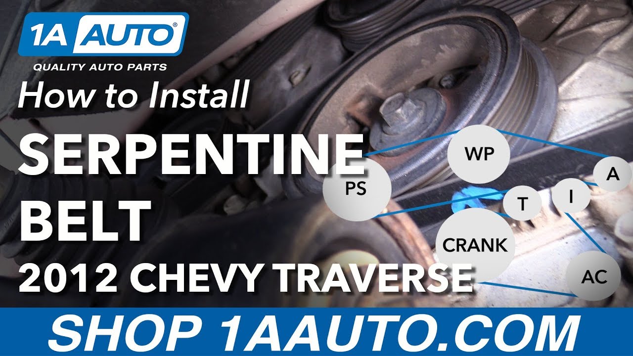
- Pulley Icons: Each pulley is represented by a circle, often with a label or abbreviation indicating its function (e.g., ALT for alternator, P/S for power steering, A/C for air conditioning).
- Tensioner Icon: The tensioner pulley is usually depicted with a spring symbol, indicating its tensioning function.
How It Works
The serpentine belt system operates on a simple principle: the rotational force from the engine's crankshaft is transferred to various accessories via a continuous belt. The crankshaft pulley drives the serpentine belt, which in turn spins the pulleys of the alternator, power steering pump, A/C compressor, and water pump. The tensioner pulley ensures that the belt remains taut, preventing slippage and maintaining optimal performance of the accessories.
The routing of the belt is meticulously engineered to provide the correct wrap angle on each pulley. Wrap angle refers to the amount of contact the belt has with the pulley's surface. Adequate wrap angle is essential for transmitting sufficient power to the accessory. Idler pulleys are strategically placed to increase wrap angles where needed and to guide the belt around other engine components.
Real-World Use: Basic Troubleshooting Tips
Here are some common issues related to the serpentine belt system and how the diagram can help with troubleshooting:
- Squealing Noise: A squealing noise, especially when starting the engine or turning the steering wheel, often indicates a slipping serpentine belt. Check the belt for cracks, wear, or glazing. Verify the tensioner pulley is functioning correctly and maintaining proper belt tension. The diagram will help you locate the tensioner and assess its operation.
- Accessory Malfunction: If the alternator, power steering, or A/C is not working correctly, inspect the serpentine belt. A broken or missing belt is an obvious culprit. If the belt is intact, ensure it is properly routed around the pulley in question. The diagram confirms this routing.
- Visual Inspection: Regularly inspect the serpentine belt for signs of wear, such as cracks, fraying, missing ribs, or glazing. These signs indicate that the belt needs replacement. Use the diagram as a reference to ensure the new belt is correctly installed.
- Belt Alignment: Misalignment of the pulleys can cause premature belt wear and accessory failure. Use a straight edge to check the alignment of the pulleys. The diagram helps identify the relative positions of the pulleys.
Safety Precautions
Working on the serpentine belt system can be hazardous. Always take the following precautions:
- Disconnect the Battery: Before working on any electrical components, disconnect the negative battery cable to prevent accidental shocks or short circuits.
- Engine Coolant Temperature: Ensure the engine is completely cool before working near the water pump or coolant hoses.
- Moving Parts: Never put your hands or tools near the serpentine belt or pulleys while the engine is running. These are extremely dangerous moving parts.
- Eye Protection: Wear safety glasses to protect your eyes from debris.
- Proper Tools: Use the correct tools for the job, such as a serpentine belt tool for releasing tension on the tensioner pulley. Using the wrong tools can damage components or cause injury.
Important Note: The tensioner pulley is spring-loaded and can snap back forcefully. Use caution when releasing the tension to avoid injury.
We have the 2010 Chevy Traverse Serpentine Belt Diagram available for download. This detailed diagram will assist you greatly in understanding and maintaining your vehicle's serpentine belt system. Please contact us to obtain the file.