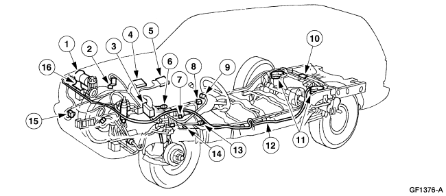
2010 Ford Expedition Rear Suspension Diagram
Alright, let's dive into the rear suspension of a 2010 Ford Expedition. This guide is for you, the DIY enthusiast or aspiring mechanic, who wants to understand how this system works, how to troubleshoot it, and how to safely work on it. Having a good grasp of the rear suspension is crucial for everything from diagnosing that annoying clunking noise to performing routine maintenance and even considering performance upgrades. And yes, we've got the diagram ready for you to download after we walk through it together.
Purpose of Understanding the Diagram
Why bother learning about the rear suspension diagram? Well, consider this: a well-maintained suspension is essential for ride comfort, vehicle handling, and overall safety. The diagram is your roadmap. It allows you to:
- Diagnose Problems: Pinpoint the source of noises, uneven tire wear, or poor handling.
- Perform Repairs: Identify parts needed for replacement and understand their location.
- Conduct Maintenance: Inspect components for wear and tear before they lead to bigger issues.
- Plan Modifications: Understand the limitations and possibilities for suspension upgrades or modifications.
- Gain Knowledge: Simply understand how your vehicle works, boosting your confidence as an owner.
Key Specs and Main Parts
The 2010 Ford Expedition typically features an independent rear suspension (IRS). This setup uses separate components for each wheel, which provides better ride quality and handling compared to a solid rear axle, although it adds complexity.
Here's a breakdown of the main parts you'll encounter in the diagram:
- Lower Control Arm: A primary structural component connecting the wheel hub assembly to the vehicle's frame. It pivots to allow for vertical wheel movement.
- Upper Control Arm (or Knuckle): Similar to the lower control arm but located higher up. Its function is to control the camber and lateral movement of the wheel. Note that depending on the specific configuration, this may be integrated into the knuckle itself.
- Wheel Hub/Bearing Assembly: This is where the wheel attaches. It houses the wheel bearing, allowing the wheel to rotate freely.
- Coil Spring: Provides the primary suspension force, absorbing bumps and keeping the vehicle at its ride height.
- Shock Absorber (Damper): Controls the oscillation of the spring. It dampens the up-and-down movement, preventing the vehicle from bouncing excessively. Sometimes the coil spring and shock absorber are combined into a coilover unit.
- Stabilizer Bar (Sway Bar): Connects the left and right sides of the suspension. It reduces body roll during cornering, improving stability.
- Brake Components: These include the brake rotor, caliper, pads, and lines. Although not directly part of the suspension, they are attached and must be considered when working on the suspension.
- Suspension Knuckle (Upright): Connects the control arms, hub assembly, and steering components (if equipped). It provides the mounting points for many suspension parts.
- Fasteners: Bolts, nuts, and bushings are crucial for connecting all the suspension components. It’s important to use the correct torque specifications when tightening them.
Understanding Symbols in the Diagram
Suspension diagrams often use standardized symbols to represent different components and connections. Knowing these symbols is key to accurately interpreting the diagram:
- Solid Lines: Typically represent rigid components like control arms, stabilizer bars, or the chassis frame.
- Dashed Lines: Often indicate hidden components or lines running behind other parts.
- Dotted Lines: Can represent the path of motion or reference lines for alignment.
- Circles/Dots: Represent joints or pivot points, such as where a control arm connects to the frame.
- Spring Symbols: A coiled line represents the coil spring.
- Shock Absorber Symbols: A rectangular box with a piston symbol typically indicates a shock absorber.
- Color Coding: Color-coding may be used to differentiate between different systems (e.g., hydraulic lines in one color, electrical lines in another). However, this is less common on suspension diagrams than on electrical schematics. Check the diagram's legend for specific color meanings.
- Arrows: Might indicate direction of movement or force.
- Numbers and Letters: These are used to identify specific parts or reference points. They often correspond to a parts list or service manual.
How It Works
The rear suspension's primary job is to allow the wheels to move independently of the vehicle's body, absorbing bumps and maintaining tire contact with the road. When a wheel encounters a bump:
- The wheel moves upward.
- This movement compresses the coil spring, which absorbs the energy of the impact.
- The shock absorber dampens the spring's oscillation, preventing the vehicle from bouncing excessively.
- The control arms guide the wheel's movement in a controlled arc, keeping the wheel aligned with the vehicle's direction.
- The stabilizer bar resists body roll during cornering by transferring force from one side of the suspension to the other.
The independent nature of the IRS means that each wheel can react to bumps independently, providing a smoother and more controlled ride compared to a solid axle setup.
Real-World Use: Basic Troubleshooting
Here's how you can use the suspension diagram to troubleshoot common issues:
- Clunking Noise: Check for worn bushings in the control arms or stabilizer bar links. The diagram helps you locate these components.
- Squeaking Noise: Could indicate dry or worn bushings. Inspect the bushings on the control arms and stabilizer bar.
- Uneven Tire Wear: May be caused by misaligned suspension. Use the diagram to identify the components that affect wheel alignment (e.g., control arms, knuckle). A professional alignment is usually necessary.
- Vehicle Leans Excessively in Turns: Could indicate a worn stabilizer bar or damaged stabilizer bar links. The diagram helps you locate and inspect these parts.
- Bouncing: Worn shock absorbers are the most likely culprit. The diagram shows their location, making inspection easier.
When troubleshooting, always start with a visual inspection. Look for obvious signs of damage, such as cracked bushings, bent components, or leaking shock absorbers. Compare what you see to the diagram to ensure everything is in its proper place.
Safety Considerations
Working on the suspension can be dangerous due to the high forces involved. Always follow these safety precautions:
- Use Jack Stands: Never work under a vehicle supported only by a jack. Always use sturdy jack stands placed on designated jacking points.
- Wear Safety Glasses: Protect your eyes from flying debris.
- Use Proper Tools: Use the correct tools for the job, including torque wrenches to ensure fasteners are tightened to the correct specifications.
- Compress Coil Springs Safely: Coil springs store a tremendous amount of energy. If you need to remove them, use a dedicated spring compressor and follow the manufacturer's instructions carefully. Incorrect spring compression can lead to serious injury or death.
- Disconnect the Battery: Before working on any electrical components, disconnect the negative battery terminal to prevent accidental shocks.
- Be Aware of Brake Lines: Brake lines are pressurized and can leak if damaged. Avoid bending or kinking them. If you need to disconnect them, have a plan for bleeding the brakes afterward.
Important note on compressed springs: Never attempt to disassemble or remove a coil spring without a proper spring compressor. These springs are under extreme pressure, and releasing them without the correct tool can be extremely dangerous, causing serious injury or even death. If you are not comfortable using a spring compressor, take the vehicle to a professional mechanic.
Working on your 2010 Ford Expedition's rear suspension can be a rewarding experience, allowing you to save money and gain a deeper understanding of your vehicle. By using the diagram and following these tips, you can safely and effectively diagnose problems, perform repairs, and keep your suspension in top condition. Now that you’ve been briefed, go ahead and download the 2010 Ford Expedition Rear Suspension Diagram. With this resource and a little elbow grease, you’ll be well on your way to mastering your vehicle’s suspension system.