2010 Ford F150 Stereo Wiring Diagram
So, you're diving into the audio system of your 2010 Ford F-150? Whether you're upgrading the head unit, installing aftermarket speakers, troubleshooting a blown fuse, or just trying to understand what wire does what, a reliable stereo wiring diagram is your best friend. This article will break down the complexities of the 2010 F-150 stereo wiring, giving you the knowledge you need to tackle your project with confidence.
Purpose of the Wiring Diagram
A stereo wiring diagram is essentially a roadmap of your vehicle's audio system. It illustrates how each component is connected, showing wire colors, connector locations, and the flow of signals. It's invaluable for:
- Repairs: Identifying faulty wiring, shorts, or open circuits.
- Upgrades: Installing aftermarket head units, amplifiers, or speakers. A diagram helps you correctly integrate these components without damaging the existing system.
- Troubleshooting: Diagnosing audio problems such as no sound, distorted audio, or issues with specific speakers.
- Learning: Understanding the layout and functionality of your truck's audio system.
Key Specs and Main Parts
Before we delve into the diagram itself, let's outline the key components of the 2010 F-150's stereo system. Keep in mind that specific features may vary depending on your trim level (XL, STX, XLT, FX4, Lariat, Platinum, King Ranch) and optional packages.
- Head Unit: This is the control center, providing radio reception, CD playback (if equipped), and often, auxiliary input or Bluetooth connectivity. The head unit sends audio signals to the speakers or, if equipped, to an amplifier.
- Speakers: Typically, the F-150 has speakers in the front doors, rear doors (if a SuperCab or SuperCrew), and sometimes tweeters mounted in the A-pillars.
- Amplifier (if equipped): Some higher-end trims come with a factory amplifier that boosts the audio signal before it reaches the speakers. Locating the amplifier is key when integrating aftermarket components.
- Wiring Harnesses: These bundles of wires connect all the components. Connectors are used to easily disconnect and reconnect parts of the system.
- Antenna: Responsible for receiving radio signals.
Common wire gauges in these systems are 16 AWG (American Wire Gauge) for speaker wires and heavier gauges for power and ground connections. Knowing these gauges is essential when splicing or extending wires.
Understanding Wiring Diagram Symbols
A wiring diagram uses a standardized set of symbols and conventions. Understanding these will allow you to correctly interpret the diagram.
- Lines: Lines represent wires. A solid line indicates a direct connection, while a dashed line might indicate a shielded wire or a connection on a different page of the diagram.
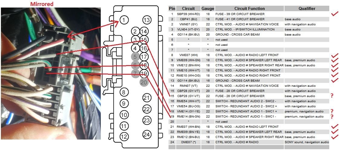
- Colors: Each wire is identified by a color code (e.g., WH/RD for White with a Red stripe). It's crucial to pay attention to these colors when making connections to avoid mistakes.
- Connectors: Represented by geometric shapes (circles, squares, rectangles), connectors show where wires join or split. Connector numbers are usually listed for easy identification.
- Ground Symbol: Typically represented by a series of downward-pointing lines or a triangle, the ground symbol indicates a connection to the vehicle's chassis, which serves as the electrical ground.
- Component Symbols: Specific symbols represent components like speakers, amplifiers, and the head unit. These symbols are often labeled with their function (e.g., "Speaker LF" for Left Front speaker).
Pay close attention to the wire gauge shown on the diagram. Using a smaller gauge than specified can lead to overheating and potentially a fire. Using a larger gauge is generally safe, though it may be unnecessarily bulky.
How It Works: The Audio Signal Path
Let's trace the path of an audio signal in a typical 2010 F-150 system:
- The head unit generates an audio signal from a radio station, CD, or auxiliary input.
- This signal is sent to the speakers (or to an amplifier, if equipped).
- If there's an amplifier, it boosts the signal's power.
- The amplified signal is then sent to the speakers, causing them to vibrate and produce sound.
The wiring diagram shows the specific connections for each step, including the power and ground connections necessary for the head unit and amplifier to function. Understanding this flow helps when troubleshooting. For example, if only one speaker isn't working, you can trace its specific wiring path to identify the fault.
Real-World Use: Basic Troubleshooting Tips
Here are a few scenarios where a wiring diagram comes in handy:
- No Sound: Check the power and ground connections to the head unit. Use a multimeter to verify that you're getting 12V power and a solid ground connection. Also, check the fuse for the radio.
- One Speaker Not Working: Use the diagram to trace the wiring from the head unit (or amplifier) to the faulty speaker. Check for loose connections, damaged wires, or a blown speaker. Swap the speaker with another known good speaker to verify the issue.
- Distorted Audio: Could be a blown speaker, a problem with the amplifier (if equipped), or a loose connection. Visually inspect the speaker for damage.
- Installing a New Head Unit: The diagram tells you which wires are power, ground, ignition, and speaker wires. This is essential for correctly connecting the new head unit without damaging your truck's electrical system.
Always test your connections with a multimeter before fully reassembling your dashboard. This can save you time and prevent potential electrical problems.
Safety Considerations
Working with automotive electrical systems can be dangerous. Always follow these safety precautions:
- Disconnect the Battery: Before working on any wiring, disconnect the negative terminal of the battery. This prevents accidental shorts and potential electrical shocks.
- Use Proper Tools: Use insulated tools designed for automotive electrical work.
- Work in a Well-Lit Area: Good visibility reduces the risk of mistakes.
- Identify Airbag Wiring: Be extremely careful when working near airbag wiring. Accidentally triggering an airbag can cause serious injury. Consult a professional if you are unsure.
The most dangerous component is the airbag system. Its wiring is usually bright yellow and clearly marked. Avoid tampering with these wires unless you are a qualified technician.
Diagram Availability
Ready to get your hands on the 2010 Ford F-150 stereo wiring diagram? We have it available for download. This detailed diagram will be an invaluable resource for your audio projects.