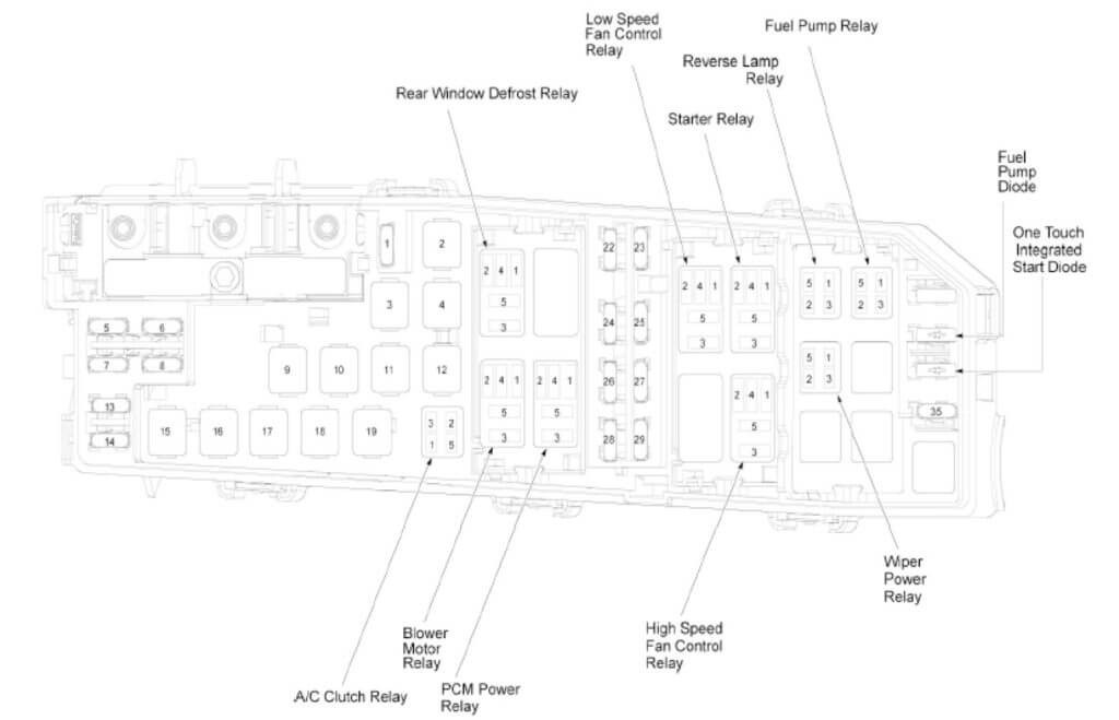
2010 Ford Focus Fuse Box Diagram Under Hood
For the experienced DIY mechanic or car enthusiast tackling electrical repairs or modifications on a 2010 Ford Focus, understanding the under-hood fuse box diagram is absolutely crucial. This document isn't just a piece of paper; it's a roadmap to your car's electrical system, allowing you to diagnose problems, replace faulty fuses, and even tap into circuits for aftermarket accessories. Without it, you're essentially working blind, potentially causing more harm than good. We're here to provide a comprehensive breakdown of that diagram, and we even have a copy available for you to download later. This article will guide you through its intricacies, making you a more confident and capable automotive technician.
Purpose of the 2010 Ford Focus Under-Hood Fuse Box Diagram
The primary purpose of the fuse box diagram is to provide a clear and concise visual representation of the fuse and relay layout within the under-hood fuse box. This diagram is indispensable for several reasons:
- Troubleshooting Electrical Issues: When an electrical component fails (e.g., a headlight, windshield wiper, or radio), the diagram helps you quickly identify the corresponding fuse or relay to check.
- Fuse Replacement: If a fuse is blown, the diagram tells you its amperage rating and function, ensuring you replace it with the correct type to avoid further damage.
- Adding Aftermarket Accessories: For those installing aftermarket accessories like driving lights, amplifiers, or security systems, the diagram allows you to safely tap into existing circuits or add new fused circuits. Understanding the function of each fuse prevents overloading existing circuits and causing potential fires.
- Understanding the Electrical System: Studying the diagram provides a deeper understanding of how various electrical components are interconnected within the vehicle.
- Preventing Further Damage: Incorrectly replacing a fuse or tampering with the wrong circuit can lead to short circuits, damage to electronic control units (ECUs), and even vehicle fires. The diagram minimizes these risks.
Key Specs and Main Parts of the Fuse Box
The under-hood fuse box, often referred to as the Power Distribution Box (PDB), houses a collection of fuses and relays responsible for protecting and controlling various electrical circuits throughout the vehicle. Let's break down the key specs and components:
- Location: The fuse box is typically located in the engine compartment, often near the battery or on the driver's side fender well. Refer to your owner's manual for the exact location.
- Fuses: Fuses are sacrificial devices designed to protect electrical circuits from overcurrent. They contain a thin wire or strip of metal that melts and breaks the circuit if the current exceeds the fuse's rated amperage.
- Relays: Relays are electromechanical switches that allow a low-current circuit to control a high-current circuit. They are used to switch power to components like headlights, fuel pumps, and starter motors. They are triggered by the PCM (Powertrain Control Module) or other control modules.
- Fuse Types: The 2010 Ford Focus typically uses a combination of blade-type fuses, including mini, standard, and maxi fuses. Each type has a different size and amperage rating.
- Amperage Ratings: Fuses are rated in amperes (amps), indicating the maximum current they can safely handle. Common amperage ratings include 5A, 7.5A, 10A, 15A, 20A, 25A, 30A, and higher. The diagram clearly indicates the amperage rating for each fuse.
Understanding Fuse Box Diagram Symbols
Fuse box diagrams use a standardized set of symbols to represent different components and connections. Familiarizing yourself with these symbols is crucial for interpreting the diagram correctly. Here's a breakdown of common symbols:
- Fuses: Fuses are typically represented by a rectangular box with a line drawn through it. The amperage rating is usually indicated next to the symbol (e.g., "15A").
- Relays: Relays are often depicted as a square or rectangular box with internal symbols representing the coil and contacts. The diagram may also indicate the relay's function (e.g., "Fuel Pump Relay").
- Lines: Solid lines represent wired connections between components. Dashed lines may indicate ground connections or signal wires.
- Colors: While not always present, some diagrams use color coding to indicate the type of circuit or voltage level. For example, red wires might represent battery power, while black wires represent ground. However, always verify wire colors with a multimeter before making any connections, as colors can vary.
- Icons: Icons are used to represent the components powered by each fuse. Common icons include headlights, wipers, radios, and various engine management components.
How It Works: The Electrical Circuit
To truly understand the fuse box diagram, it's essential to grasp the basics of an electrical circuit. A circuit consists of a power source (battery), a conductor (wire), a load (the component being powered), and a return path to the power source (ground). The fuse is placed in the circuit to protect the load from overcurrent.
When the switch for a particular component is turned on (e.g., headlights), current flows from the battery, through the fuse, to the component, and then back to the battery through the ground connection. If there's a short circuit (an unintended path for current to flow, bypassing the load), the current will increase dramatically. This excessive current causes the fuse to blow, interrupting the circuit and preventing damage to the component and wiring.
Relays, on the other hand, act as remote-controlled switches. A small current from a control module (like the PCM) energizes the relay coil, which then closes the relay contacts, allowing a larger current to flow to the component being controlled (e.g., the fuel pump). This allows the PCM to control high-current devices without directly handling the high current.
Real-World Use: Basic Troubleshooting Tips
Here are some basic troubleshooting tips using the fuse box diagram:
- Component Not Working: If a component isn't working, the first step is to consult the fuse box diagram and identify the corresponding fuse. Use a fuse tester or multimeter to check if the fuse is blown. If it is, replace it with a fuse of the same amperage rating.
- Fuse Keeps Blowing: If a fuse blows repeatedly, there's likely a short circuit in the corresponding circuit. Don't simply replace the fuse with a higher amperage fuse, as this can damage the wiring and components. Instead, trace the wiring for that circuit, looking for damaged insulation, pinched wires, or faulty components.
- Relay Problems: If a component isn't working and the fuse is good, the relay might be faulty. You can test a relay by swapping it with a known good relay of the same type. You can also use a multimeter to check the relay's coil and contacts for continuity.
- Using a Multimeter: A multimeter is an invaluable tool for electrical troubleshooting. It can be used to check for voltage, current, and resistance. Refer to your multimeter's manual for instructions on how to use it properly.
Safety: Risky Components and Precautions
Working with automotive electrical systems can be dangerous if proper precautions are not taken. Here are some key safety considerations:
- Disconnect the Battery: Before working on any electrical component, always disconnect the negative (-) terminal of the battery. This will prevent accidental short circuits and electrical shocks.
- High-Voltage Components: Be extremely cautious around high-voltage components, such as the ignition coil and spark plugs. These components can deliver a painful and potentially lethal shock, even with the battery disconnected if capacitors are storing charge.
- Airbag System: The airbag system is extremely sensitive and can deploy unexpectedly if mishandled. Do not tamper with the airbag system unless you are a qualified technician.
- Fuel System: Working around the fuel system can be hazardous due to the risk of fire. Disconnect the fuel pump relay before working on the fuel system and take precautions to prevent sparks or open flames.
- Proper Tools: Use insulated tools designed for automotive electrical work.
- Consult a Professional: If you are unsure about any aspect of electrical troubleshooting or repair, consult a qualified automotive technician. It's always better to be safe than sorry.
Remember to always consult your vehicle's repair manual for specific instructions and safety procedures. With a good understanding of the 2010 Ford Focus under-hood fuse box diagram and proper safety precautions, you can confidently tackle a wide range of electrical repairs and modifications.
As promised, we have the 2010 Ford Focus Under-Hood Fuse Box Diagram available for download. Use it responsibly and safely!