2010 Nissan Altima Alternator Wiring Diagram
The 2010 Nissan Altima's alternator is a critical component of the vehicle's electrical system. It's responsible for charging the battery and providing power to all the electrical accessories while the engine is running. Understanding the alternator wiring diagram is crucial for troubleshooting electrical issues, performing repairs, or even planning modifications to your car's electrical system. This article breaks down the 2010 Altima alternator wiring diagram, explaining its components, how it works, and some basic troubleshooting tips. We have the actual file, and you can download the complete diagram using the link at the end of this article.
Purpose of the Alternator Wiring Diagram
The wiring diagram serves as a roadmap for the electrical circuits connected to the alternator. Its purpose is multi-faceted:
- Troubleshooting: When electrical problems arise, the diagram helps trace the flow of electricity, pinpointing faults like short circuits, open circuits, or loose connections.
- Repair and Replacement: If you need to replace the alternator or any related wiring, the diagram ensures correct reconnection and avoids potential damage.
- Modification and Upgrades: For those looking to add electrical accessories or upgrade the charging system, the diagram provides essential information about the existing wiring and the alternator's capabilities.
- Understanding the System: Even without immediate problems, studying the diagram enhances your understanding of your car's electrical system.
Key Specs and Main Parts
Before diving into the wiring diagram, it's essential to understand the key specs and parts of the alternator system. The 2010 Altima's alternator is a traditional automotive alternator using a voltage regulator to manage its output.
- Alternator: The heart of the system. Its job is to convert mechanical energy from the engine's rotation into electrical energy (AC, which is then rectified to DC). The 2010 Altima likely uses either a 110 Amp or 130 Amp alternator, depending on the trim level and options. Check your vehicle's documentation to confirm the amperage rating.
- Battery: Provides initial power to start the engine and acts as a reservoir for electrical energy. It also stabilizes the voltage in the system.
- Voltage Regulator: A crucial component that controls the alternator's output voltage. It prevents overcharging the battery and ensures a consistent voltage for the car's electrical components. The regulator is usually integrated into the alternator itself.
- Wiring Harness: A collection of wires bundled together to connect the alternator to the battery, ignition system, and other electrical components.
- Fuses and Relays: Protective devices that safeguard the electrical circuits from overloads and short circuits. The alternator circuit is typically protected by a high-amperage fuse (often a fusible link).
- Serpentine Belt: Drives the alternator pulley, transferring mechanical energy from the engine.
- Ground Connection: A vital connection to the vehicle's chassis, providing a return path for the electrical current. A poor ground connection can cause a multitude of electrical problems.
Symbols and Conventions in the Wiring Diagram
Wiring diagrams use standardized symbols to represent electrical components and connections. Understanding these symbols is crucial for interpreting the diagram correctly.
- Solid Lines: Represent wires. Thicker lines often indicate wires carrying higher currents.
- Dashed Lines: May indicate shielded wiring or wires within a harness.
- Circles: Can represent various components depending on what is inside the circle. They could signify lamps, sensors, or other devices.
- Rectangles: Often represent electrical components like relays, modules, or control units.
- Ground Symbol: Typically represented by a series of horizontal lines decreasing in length, signifies a connection to the vehicle's chassis ground.
- Battery Symbol: A series of alternating long and short lines, indicating the positive and negative terminals.
- Fuse Symbol: A wavy line or a small rectangle with a diagonal line through it, indicating a fuse.
Color Coding: Wiring diagrams use color codes to identify individual wires. For example, a wire labeled "B" is typically black (ground), "R" is red (power), "W" is white, "BL" is blue, "G" is green, "Y" is yellow, "BR" is brown, and "OR" is orange. Knowing the color code can greatly simplify tracing wires within the harness.
How the Alternator Circuit Works
The alternator circuit in the 2010 Altima operates as follows:
- Starting the Engine: When you turn the ignition key, the battery provides power to the starter motor, which cranks the engine.
- Engine Running: Once the engine starts, the serpentine belt drives the alternator pulley, causing the alternator to generate AC electricity.
- Rectification: The AC electricity generated by the alternator is converted to DC electricity by diodes within the alternator.
- Voltage Regulation: The voltage regulator monitors the battery's voltage and adjusts the alternator's output to maintain a constant charging voltage (typically around 13.5-14.5 volts).
- Charging the Battery: The DC electricity from the alternator charges the battery, replenishing the energy used during engine starting.
- Powering Accessories: The alternator also provides power to all the car's electrical accessories, such as the headlights, radio, air conditioning, and power windows.
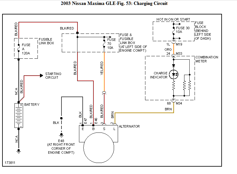
The wiring diagram will show the following key connections:
- Battery (B+) Terminal: A heavy-gauge wire connecting the alternator's positive terminal (B+) directly to the battery's positive terminal. This wire carries the charging current.
- Ignition (IG) Terminal: This terminal receives a signal from the ignition switch, telling the alternator when the engine is running and to start charging.
- Sense (S) Terminal: This terminal is used by the voltage regulator to monitor the battery's voltage. It may be connected directly to the battery positive terminal, or to a point in the electrical system closer to the loads (for better voltage regulation).
- Ground Terminal: A solid ground connection to the vehicle's chassis, providing a return path for the current.
Real-World Use and Basic Troubleshooting
Here are some common issues and troubleshooting tips using the wiring diagram:
- Battery Not Charging: Check the B+ wire for continuity and proper connection at both the alternator and battery terminals. Verify the alternator fuse is not blown. Use a multimeter to measure the voltage at the alternator's B+ terminal with the engine running. It should be above the battery voltage and within the 13.5-14.5 volt range.
- Overcharging: An overcharging battery can be caused by a faulty voltage regulator. Replacing the alternator (which usually includes the regulator) is often the best solution. However, check the "Sense" wire; if it's disconnected or has a high resistance, the regulator might incorrectly increase the output.
- Warning Light On: The "charge" or "battery" warning light on the dashboard indicates a problem in the charging system. Use the wiring diagram to trace the circuit from the alternator to the instrument cluster. Check for loose connections, damaged wires, or a faulty alternator.
- Excessive Noise: A whining or screeching noise from the alternator area can indicate a worn-out bearing or a loose serpentine belt. The wiring diagram won't directly help with this, but it can help you identify the alternator's location and access it for inspection.
Safety Precautions
Working on the electrical system of a car can be dangerous. Observe the following safety precautions:
- Disconnect the Battery: Always disconnect the negative battery terminal before working on any electrical components. This prevents accidental short circuits and electrical shocks.
- Work in a Well-Ventilated Area: Battery acid can release hydrogen gas, which is flammable.
- Use Proper Tools: Use insulated tools designed for automotive electrical work.
- Avoid Touching Exposed Wires: Be careful not to touch any exposed wires or terminals while the battery is connected.
- The B+ Terminal: The B+ terminal on the alternator is always live when the battery is connected. Accidental shorting of this terminal to ground can cause a large spark and damage to the electrical system. Be extremely careful when working around this terminal.
By carefully studying the 2010 Nissan Altima alternator wiring diagram and following these troubleshooting tips and safety precautions, you can diagnose and repair many common charging system problems. We have the actual file, and you can download the complete diagram here. (Placeholder link for the actual diagram file). Remember to always consult your vehicle's repair manual for specific instructions and torque specifications.