2010 Nissan Altima Fuse Box Diagram
For the experienced DIYer tackling electrical issues in a 2010 Nissan Altima, a clear understanding of the fuse box diagram is absolutely essential. It's the roadmap to navigating the car's electrical system. This isn't just about replacing a blown fuse; it's about understanding the circuits, tracing problems, and even safely adding aftermarket accessories. This article delves into the 2010 Altima's fuse box, breaking down its components, symbols, and practical applications, giving you the knowledge to confidently diagnose and fix electrical issues.
Purpose of the Fuse Box Diagram
Why bother with a fuse box diagram? Well, consider this: without it, you're essentially blindfolded in a maze of wires and components. The diagram serves several critical purposes:
- Troubleshooting Electrical Problems: When a component fails (like a headlight or power window), the diagram helps you quickly identify the corresponding fuse and relay. If the fuse is blown, it points you to the affected circuit, allowing you to trace the fault.
- Performing Repairs: The diagram helps you locate and test circuits without blindly probing wires. This is crucial when replacing components or repairing damaged wiring.
- Installing Accessories: If you're adding aftermarket accessories like a new stereo or auxiliary lighting, you need to tap into the car's electrical system safely. The diagram helps you identify suitable circuits and ensure proper fusing to prevent overloads and potential fires.
- Understanding Vehicle Systems: Even if you're not actively working on your car, understanding the fuse box layout provides valuable insight into how the vehicle's electrical systems are organized and protected.
Key Specs and Main Parts
The 2010 Nissan Altima typically has two main fuse box locations:
Interior Fuse Box
Located usually under the dashboard, often on the driver's side near the steering column, this fuse box primarily houses fuses and relays for interior components such as:
- Interior lighting
- Power windows
- Power locks
- Radio/stereo system
- Windshield wipers
- Cigarette lighter/power outlets
Engine Compartment Fuse Box
Located under the hood, usually near the battery, this fuse box protects critical engine and drivetrain components, including:
- Engine control unit (ECU) – the car's brain
- Fuel pump
- Ignition system
- Headlights and taillights
- Cooling fan
- Anti-lock braking system (ABS)
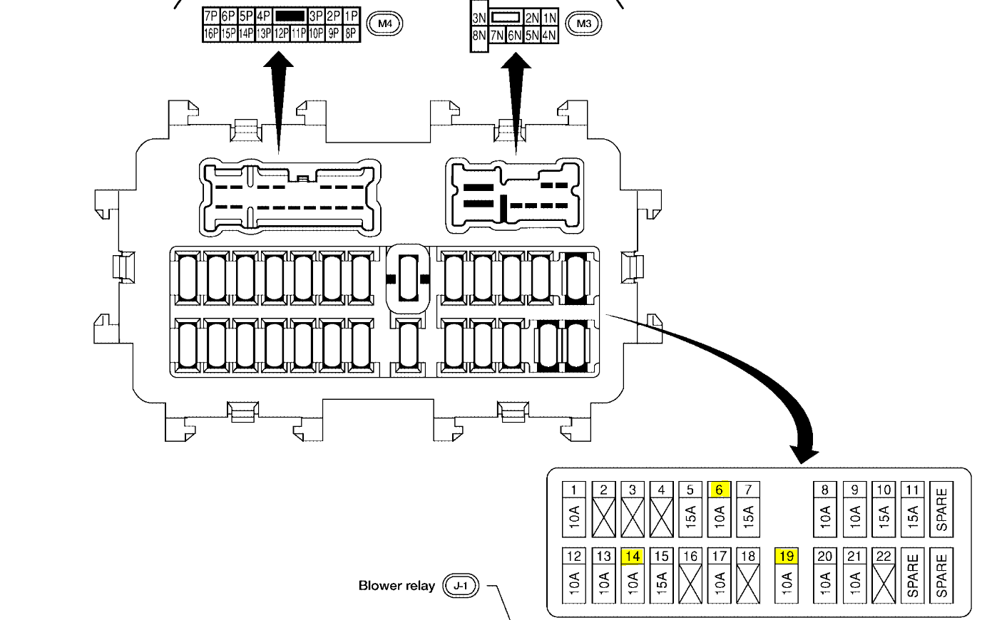
Key Specs: While the physical dimensions and layout of the fuse boxes are important, the most crucial specifications are the fuse amperage ratings. Each fuse is designed to protect a specific circuit by interrupting the current flow if it exceeds a certain level. These ratings are clearly marked on the fuses themselves (e.g., 5A, 10A, 15A, 20A, 25A, 30A). Using a fuse with a higher amperage rating than specified can lead to serious damage or even a fire, as it won't protect the circuit as intended.
Understanding the Symbols and Layout
Fuse box diagrams aren't just pictures; they're coded representations of the electrical system. Here's how to decipher them:
Fuse Symbols
Typically, fuses are represented by a small rectangle with a number indicating the amperage. Some diagrams may use slightly different symbols, but the amperage rating is always clearly marked.
Relay Symbols
Relays, which act as electrically controlled switches, are usually depicted as a square or rectangle with internal lines representing the coil and contacts. Understanding relay symbols is important because relays often control high-current circuits, allowing a low-current signal from a switch to activate a high-current device like a starter motor or headlight.
Lines and Colors
The lines in the diagram represent the wiring connecting the fuses and relays to the various components. Color-coding, if present, can indicate different voltage levels or circuit functions. However, be cautious relying solely on color codes, as they can vary over time or due to previous repairs.
Component Icons
The diagram may also include simplified icons representing the components being protected (e.g., a light bulb for headlights, a fan for the cooling fan, etc.).
Diagram Layout
The diagram's layout mirrors the physical arrangement of the fuses and relays in the fuse box. This makes it easier to locate the correct component. Each fuse and relay position is typically numbered or labeled, corresponding to the diagram.
How It Works: The Underlying Principle
The fuse box's primary function is circuit protection. Each fuse is a sacrificial component designed to break the circuit if the current exceeds its rated amperage. This prevents damage to the wiring and components connected to that circuit.
Imagine a garden hose (the wiring) connected to a faucet (the battery) and a sprinkler (the component). If there's a kink in the hose (a short circuit) or too much water pressure (an overload), the hose could burst. The fuse acts like a valve that automatically shuts off the water flow if the pressure gets too high, preventing the hose from bursting.
Relays, on the other hand, act as remote-controlled switches. They allow a low-current signal (e.g., from a switch on the dashboard) to control a high-current circuit (e.g., the headlights). This is important because directly routing high-current wires to the dashboard switches would require bulky wiring and could pose a safety hazard.
Real-World Use: Basic Troubleshooting Tips
Here's how to use the fuse box diagram to troubleshoot common electrical problems:
- Identify the Symptom: What's not working? Headlights? Power windows? Locate the corresponding component in the diagram.
- Locate the Fuse: Use the diagram to find the fuse associated with the malfunctioning component.
- Inspect the Fuse: Visually inspect the fuse. A blown fuse will have a broken filament. You can also use a multimeter to test the fuse's continuity. Set your multimeter to the continuity setting (usually indicated by a sound wave symbol) and touch the probes to each end of the fuse. If the multimeter beeps or shows a low resistance reading, the fuse is good. If it doesn't, the fuse is blown.
- Replace the Fuse: Replace the blown fuse with a new fuse of the same amperage rating. Never use a fuse with a higher amperage.
- Test the Circuit: After replacing the fuse, test the component. If the fuse blows again immediately, there's a short circuit or overload in the circuit that needs to be diagnosed and repaired by a qualified mechanic. Do not keep replacing fuses without addressing the underlying issue.
- Check the Relays: If replacing the fuse doesn't solve the problem, the relay might be faulty. Use the diagram to locate the relay and test it using a multimeter or swap it with a known good relay of the same type.
Safety Considerations
Working with automotive electrical systems can be dangerous. Here are some important safety precautions:
- Disconnect the Battery: Before working on any electrical components, disconnect the negative terminal of the battery. This will prevent accidental short circuits and shocks.
- Use the Right Tools: Use insulated tools designed for automotive electrical work.
- Never Bypass Fuses: Never bypass a fuse with a wire or other conductive material. This can cause a fire.
- Avoid Water: Never work on electrical components in wet conditions.
- Identify High-Risk Components: Be particularly cautious around the airbag control module and the ABS system. Improper handling of these components can cause serious injury. Always consult a professional mechanic if you're unsure about working on these systems.
Understanding the 2010 Nissan Altima fuse box diagram empowers you to diagnose and resolve common electrical issues. With careful observation, the right tools, and a methodical approach, you can confidently tackle these repairs and maintenance tasks. Remember, if you encounter a complex electrical problem or are unsure about any procedure, it's always best to consult a qualified mechanic.
We have a high-resolution PDF file of the 2010 Nissan Altima Fuse Box Diagram available for download. This diagram will provide a more detailed and clearer view of the fuse and relay locations. Use it to enhance your understanding and assist in your troubleshooting efforts. Download it for convenient access when you need it most.