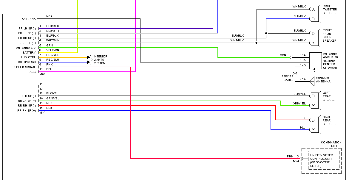
2010 Nissan Altima Radio Wiring Diagram
So, you're looking at the radio wiring diagram for a 2010 Nissan Altima. Excellent! Understanding this wiring layout is invaluable whether you're upgrading your sound system, troubleshooting a dead radio, or just trying to understand how your car's electrical system works. This isn't just about plugging things in; it's about understanding the language of electrons flowing through your Altima.
Purpose of the 2010 Nissan Altima Radio Wiring Diagram
Why bother with this diagram? Several reasons:
- Aftermarket Radio Installation: This is the big one. Swapping out your factory radio for a shiny new aftermarket unit requires knowing exactly which wire does what. Messing this up can lead to blown fuses, fried electronics, or worse.
- Troubleshooting: No sound? Radio won't turn on? Knowing where to start looking is half the battle. The wiring diagram guides you through the circuit, helping you pinpoint the source of the problem.
- Speaker Upgrades: Upgrading speakers often involves tapping into existing wiring. This diagram lets you identify the correct speaker wires, avoiding any damage to other components.
- Learning: Even if you don't plan on doing any work right now, understanding the diagram is a great way to learn about your car's electrical system.
Key Specs and Main Parts
Before diving into the maze of wires, let's cover some crucial specifications and components you'll encounter in the 2010 Nissan Altima radio system:
- Voltage: Primarily 12V DC (Direct Current). Automotive systems operate on a 12-volt standard.
- Ground (Chassis Ground): The negative terminal of the car's electrical system, usually connected to the car's metal frame. It is extremely important that this is secure.
- Battery (B+ or Constant Power): Provides power to the radio to maintain memory settings (like presets) even when the ignition is off.
- Ignition (Switched Power): Provides power to the radio only when the ignition is turned on.
- Speakers: Usually four (front left, front right, rear left, rear right), each with a positive (+) and negative (-) wire.
- Antenna: Connects to the car's antenna to receive radio signals. The antenna wire is typically a coaxial cable.
- Steering Wheel Controls (if equipped): Wires that allow you to control the radio volume, track selection, etc., from the steering wheel. Often utilize a resistance-based system.
- Amplifier (if equipped): Some Altimas came with a factory amplifier. If present, the wiring diagram will show the connections between the radio and the amplifier, as well as the amplifier and the speakers.
Decoding the Symbols and Color Codes
The diagram itself is a visual language. Here's a guide to understanding the common symbols and color codes:
- Lines: Represent wires. Thicker lines might indicate a wire with a higher current carrying capacity.
- Colors: Each wire color represents a specific function. Common colors include:
- Red: Usually battery (B+) or constant power.
- Yellow: Typically ignition (switched power).
- Black: Almost always ground.
- White: Often used for speaker wires. The color is sometimes followed by a stripe (e.g., White/Red).
- Blue: Remote Turn-On for aftermarket amplifiers.
- Circles/Dots: Represent wire connectors or junctions.
- Rectangles: Represent components like the radio head unit, amplifier, or speakers.
- Ground Symbol: Looks like an upside-down triangle with horizontal lines. Indicates a ground connection.
- Fuse Symbol: A squiggly line enclosed in a rectangle. Indicates a fuse in the circuit.
- Abbreviations:
- B+: Battery positive.
- GND: Ground.
- ACC: Accessory (ignition switched power).
- REM: Remote.
How It Works: The Radio Circuit
The radio circuit in your Altima is relatively straightforward:
- Power Supply: The battery (B+) provides constant power to the radio for memory functions. The ignition switch provides power when the car is turned on.
- Grounding: The radio is grounded to the car's chassis, completing the electrical circuit.
- Input Signals:
- Antenna: Receives radio signals.
- Steering Wheel Controls: Sends signals to the radio when buttons are pressed on the steering wheel.
- Output Signals: The radio processes the input signals and sends audio signals to the speakers. If an amplifier is present, the radio sends a lower-level signal to the amplifier, which then amplifies the signal and sends it to the speakers.
Real-World Use: Basic Troubleshooting Tips
Here's how you can use the wiring diagram for troubleshooting:
- No Power: Use a multimeter to check for voltage at the B+ and ignition wires at the radio connector. If no voltage is present, check the corresponding fuses. Consult your owner's manual for fuse locations.
- No Sound: Verify that the radio is receiving power and that the speakers are properly connected. Use the wiring diagram to identify the speaker wires and check their continuity with a multimeter. If an amplifier is present, check its power and ground connections.
- Weak Reception: Check the antenna connection at the radio. Make sure the antenna wire is not damaged.
- Steering Wheel Controls Not Working: Check the wiring connections for the steering wheel control interface (if applicable). The interface may need to be programmed or reset.
Safety First!
Working with electrical systems in a car can be dangerous. Here are some crucial safety precautions:
- Disconnect the Battery: Always disconnect the negative terminal of the car battery before working on the electrical system. This prevents accidental shorts and potential shocks.
- Use a Multimeter: A multimeter is your best friend. Use it to check for voltage, continuity, and resistance.
- Work in a Well-Lit Area: Good visibility is essential.
- Don't Cut Wires Blindly: Always identify the wires using the wiring diagram before cutting or splicing them.
- Insulate Connections: Use electrical tape or heat shrink tubing to insulate all wire connections.
- Be Aware of Airbag Wires: Avoid tampering with any wires that are colored yellow, as these are usually related to the airbag system. Mishandling these wires can cause the airbags to deploy, resulting in serious injury.
- Fuses are Important If a fuse blows, replace it with a fuse of the same amperage rating. Using a fuse with a higher amperage rating can damage the electrical system.
Remember, working on your car's electrical system requires a certain level of knowledge and skill. If you're not comfortable with any of these procedures, it's best to consult a professional.
We have the full 2010 Nissan Altima Radio Wiring Diagram available for download. This diagram includes detailed schematics and color codes, making it an invaluable resource for your project.