2010 Nissan Rogue Fuse Box Diagram
For the intermediate car owner or DIY mechanic, understanding your vehicle's electrical system is paramount for effective repairs, modifications, and general maintenance. One crucial element within this system is the fuse box. This article provides a detailed explanation of the 2010 Nissan Rogue fuse box diagram, equipping you with the knowledge to diagnose electrical issues and perform safe, informed repairs.
Purpose of the 2010 Nissan Rogue Fuse Box Diagram
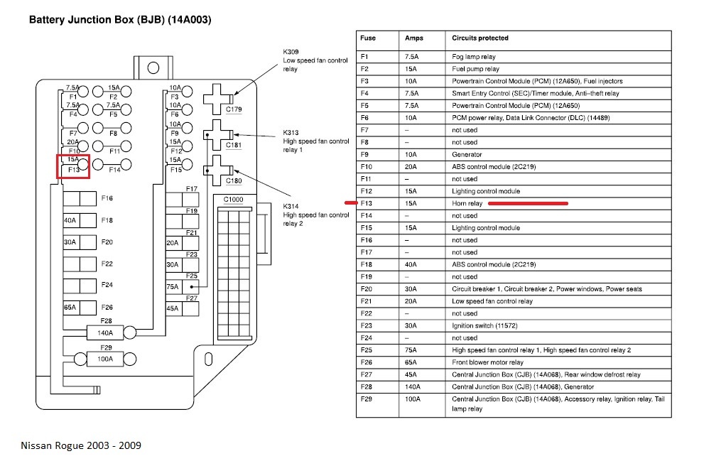
The fuse box diagram is essentially a map of your vehicle's electrical protection system. It tells you the location of each fuse and relay, what circuit it protects, and its amperage rating. Why is this important? Consider these scenarios:
- Electrical Failure: A taillight suddenly stops working, or the radio goes silent. The first step is to check the relevant fuse. The diagram pinpoints its exact location.
- Accessory Installation: Adding aftermarket lights, a sound system, or a dashcam requires tapping into the electrical system. Knowing the fuse layout helps you choose a safe and appropriate circuit to connect to.
- Learning Your Vehicle: Understanding the fuse box provides a deeper insight into the overall electrical design of your Rogue.
Without the diagram, you're essentially troubleshooting in the dark. It saves time, prevents misdiagnosis, and reduces the risk of further damage.
Key Specs and Main Parts of the Fuse Box
The 2010 Nissan Rogue typically has two primary fuse box locations:
- Interior Fuse Box: Located inside the cabin, usually under the dashboard on the driver's side. This box generally houses fuses for interior components like lights, radio, power windows, and accessories.
- Engine Compartment Fuse Box: Found in the engine bay, often near the battery. This box protects vital engine systems such as the fuel pump, ignition system, headlights, and cooling fan.
Within each fuse box, you'll find the following:
- Fuses: These are the sacrificial components. They are designed to blow (open the circuit) when an excessive current flows through them, protecting more expensive components from damage. Fuses are rated in amperes (amps), which indicate the maximum current they can handle before blowing.
- Relays: These are electromechanical switches that control high-current circuits using a low-current signal. They are used to switch on headlights, the starter motor, and other high-demand systems.
- Fuse Puller: A small plastic tool often included in the fuse box to safely remove fuses. Using pliers can damage the fuse box or the fuse itself.
- Spare Fuses: Some fuse boxes include a few spare fuses of different amperage ratings.
- Cover/Lid: The cover protects the fuses and often has a printed diagram on its inner surface.
Understanding the Symbols in the Diagram
Fuse box diagrams use symbols and conventions to represent different components and circuits. These symbols are largely standardized across manufacturers, but some variations may exist. Here are common symbols and their meanings:
- Lines: Lines represent electrical wires or circuits. Thicker lines might indicate higher current capacity.
- Boxes: Rectangular boxes generally represent fuses or relays.
- Numbers: Numbers indicate the fuse or relay number within the box. This number is crucial for identifying the correct fuse on the diagram.
- Amperage Rating: Each fuse is marked with its amperage rating (e.g., 10A, 15A, 20A). This indicates the maximum current the fuse can handle.
- Component Icons: Specific icons represent the component the fuse protects. Common icons include:
- Lightbulb: Headlights, taillights, interior lights
- Radio: Audio system
- Fan: Cooling fan, blower motor
- Engine: Engine control unit (ECU) or other engine-related systems
- Window: Power windows
- Colors: While not always present on the diagram itself, fuses are color-coded according to their amperage rating (e.g., yellow = 20A, blue = 15A, red = 10A).
The diagram also identifies the circuit each fuse protects. For example, "Taillights" or "Fuel Pump" will be listed next to the fuse designation.
How It Works: The Electrical Circuit and Fuse Protection
To understand how the fuse box works, it's essential to grasp the basics of an electrical circuit. A circuit is a closed loop through which electricity flows. It consists of a power source (e.g., battery), a load (e.g., a headlight), and wires connecting them.
The fuse is inserted in this circuit. Its primary function is to protect the circuit from overcurrent. When an excessive current flows, typically due to a short circuit or a component malfunction, the fuse's internal element (a thin wire or strip) heats up rapidly and melts, breaking the circuit. This interruption prevents damage to the wiring, components, and potentially, a fire.
The relay acts as a remote switch. A small current from the control circuit energizes the relay's coil, creating a magnetic field that pulls a switch closed. This allows a larger current from a separate, high-current circuit to flow to the intended load. This is crucial for components that draw significant power, as it prevents the need for heavy-gauge wiring throughout the vehicle.
Real-World Use: Basic Troubleshooting Tips
Here's a basic troubleshooting process using the fuse box diagram:
- Identify the Problem: Determine which component is malfunctioning (e.g., the cigarette lighter doesn't work).
- Consult the Diagram: Locate the fuse associated with the malfunctioning component on the fuse box diagram.
- Locate the Fuse: Find the physical fuse in the fuse box, using the diagram's numbering system.
- Inspect the Fuse: Visually inspect the fuse. A blown fuse will have a broken filament inside.
- Test the Fuse (Optional): Use a multimeter set to continuity mode to test the fuse. A working fuse will show continuity (a beep or a low resistance reading). A blown fuse will show no continuity.
- Replace the Fuse: If the fuse is blown, replace it with a new fuse of the same amperage rating. Never use a fuse with a higher amperage rating, as this can bypass the intended protection and lead to damage.
- Test the Circuit: After replacing the fuse, test the component to see if it now works.
- If the Fuse Blows Again: If the new fuse blows immediately, there is likely a short circuit or a more serious problem in the wiring or the component itself. This requires further diagnosis, potentially by a qualified mechanic.
Safety Precautions
Working with electrical systems can be dangerous. Here are some crucial safety precautions:
- Disconnect the Battery: Before working on any electrical components, disconnect the negative (-) terminal of the battery to prevent accidental shorts.
- Use Insulated Tools: Use tools with insulated handles to avoid electric shock.
- Never Replace a Fuse with a Higher Amperage: As mentioned earlier, this can bypass the intended protection and lead to serious damage or fire.
- Be Careful with Relays: Relays can get hot when energized. Allow them to cool before handling them.
- If Unsure, Seek Professional Help: If you are not comfortable working with electrical systems, consult a qualified mechanic.
- High-Risk Components: Pay extra attention when working around components related to the SRS (Supplemental Restraint System, i.e., airbags) and the fuel system. Incorrect handling can trigger airbag deployment or fuel leaks, both of which are extremely dangerous.
Understanding the 2010 Nissan Rogue fuse box diagram empowers you to maintain and repair your vehicle's electrical system safely and effectively. With a bit of knowledge and the right tools, you can diagnose and fix common electrical issues, saving time and money. Remember to prioritize safety and seek professional assistance when needed.
We have a complete, high-resolution PDF of the 2010 Nissan Rogue Fuse Box Diagram available for download. It provides detailed information and clear visuals to assist you in your troubleshooting and repair endeavors.