2010 Nissan Versa Fuse Box Diagram
For the experienced DIYer tackling electrical issues on a 2010 Nissan Versa, a reliable fuse box diagram is an absolute necessity. This isn't just a piece of paper; it's your roadmap to understanding and diagnosing electrical faults, safely performing modifications, and gaining a deeper insight into your vehicle's intricate systems. Whether you're dealing with a blown headlight, a malfunctioning power window, or planning to install aftermarket accessories, mastering the fuse box layout is paramount.
Purpose of a Fuse Box Diagram
Why is a fuse box diagram so important? The answer is multifaceted:
- Troubleshooting Electrical Issues: When an electrical component fails, the first step is often checking the corresponding fuse. The diagram tells you exactly which fuse to inspect, saving you time and preventing misdiagnosis.
- Preventing Further Damage: Replacing a blown fuse with one of a higher amperage (the measure of electrical current) can overload the circuit and cause serious damage, including electrical fires. The diagram confirms the correct amperage rating for each fuse.
- Installing Aftermarket Accessories: Tapping into existing circuits for new accessories, like a stereo or auxiliary lighting, requires identifying appropriate power sources and using the correct fuses. The diagram shows you available circuits and their current capacity.
- Understanding Vehicle Systems: Studying the fuse box layout provides a basic understanding of how different electrical components are interconnected and powered.
- General Maintenance: The fuse box is susceptible to corrosion and damage. Regular inspection and cleaning, guided by the diagram, ensures optimal electrical performance.
Key Specs and Main Parts of the 2010 Versa Fuse Box
The 2010 Nissan Versa typically has two main fuse boxes:
- Interior Fuse Box: Located inside the cabin, usually under the dashboard on the driver's side or behind the glove compartment. This box primarily houses fuses for interior components like lights, radio, power windows, and the climate control system.
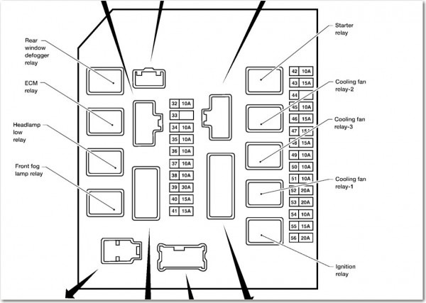
- Engine Compartment Fuse Box: Found in the engine bay, near the battery. This box contains fuses and relays for critical engine management systems, headlights, horn, and the starting circuit.
Key specifications related to the fuse box include:
- Fuse Types: The Versa typically uses blade-type fuses, often referred to as ATO or APR fuses. These are available in various sizes and amperage ratings (e.g., 5A, 7.5A, 10A, 15A, 20A, 25A, 30A).
- Fuse Amperage Ratings: Each fuse is designed to handle a specific current. Replacing a fuse with the correct amperage is crucial for safety and proper system operation.
- Relays: These are electromechanical switches that control high-current circuits using a low-current control signal. They are often used for headlights, horns, and starter motors.
- Circuit Breakers: Some circuits may be protected by circuit breakers, which automatically reset after a short circuit or overload is cleared.
Decoding Fuse Box Diagram Symbols
A fuse box diagram isn't just a random arrangement of squares and rectangles. It uses specific symbols and conventions to represent different components and their functions. Understanding these symbols is essential for interpreting the diagram correctly.
- Lines: Lines represent electrical wires connecting different components. A solid line indicates a direct connection, while a dashed line might indicate a ground connection or a less direct path.
- Colors: Wire colors are often indicated on the diagram. These colors correspond to the actual wire colors in your vehicle, helping you trace circuits and identify specific wires. Common colors include red (power), black (ground), and various other colors for signal and control circuits.
- Fuse Symbol: Typically a rectangle with a squiggly line inside, representing the fuse element. The amperage rating is usually printed next to the fuse symbol.
- Relay Symbol: Often depicted as a square or rectangle with internal symbols representing the coil and contacts of the relay.
- Component Symbols: Various symbols represent the components protected by the fuses, such as headlights (circle with a filament symbol), horns (stylized horn shape), and various electrical motors.
- Ground Symbol: Usually three horizontal lines decreasing in size, indicating a connection to the vehicle's chassis for grounding.
It's important to note that different diagrams might use slightly different symbols. Consulting the legend accompanying the diagram is always recommended.
How It Works: The Fuse Protection System
Fuses act as sacrificial elements in an electrical circuit. They are designed to intentionally blow (open the circuit) if the current exceeds the rated amperage. This protects the more expensive and critical components in the circuit from damage caused by overloads or short circuits.
A short circuit occurs when a wire accidentally comes into contact with ground, creating a low-resistance path for current to flow. This results in a very high current, which quickly overheats and melts the fuse element, breaking the circuit.
An overload happens when a circuit is drawing more current than it's designed to handle. This could be caused by a faulty component or by connecting too many devices to the same circuit. The excessive current will eventually overheat and blow the fuse.
When a fuse blows, it indicates that something is wrong in the circuit. Simply replacing the fuse without addressing the underlying issue will likely result in the new fuse blowing as well.
Real-World Use: Basic Troubleshooting Tips
Here's a basic troubleshooting procedure using the fuse box diagram:
- Identify the Problem: Determine which electrical component is not working.
- Consult the Diagram: Locate the fuse that corresponds to the malfunctioning component on the fuse box diagram. The diagram will specify the fuse number and amperage.
- Inspect the Fuse: Remove the fuse and visually inspect it. A blown fuse will usually have a broken filament or a dark, burnt appearance inside the glass or plastic housing.
- Replace the Fuse: If the fuse is blown, replace it with a new fuse of the identical amperage rating. Never use a fuse with a higher amperage.
- Test the Component: After replacing the fuse, test the component to see if it's working again.
- Investigate if the Fuse Blows Again: If the new fuse blows immediately or shortly after, there is a more serious problem in the circuit that needs to be investigated by a qualified mechanic.
For example, if your headlights aren't working, you would consult the fuse box diagram to find the fuse for the headlights. Then, you'd check the fuse to see if it's blown. If it is, you'd replace it with a new fuse of the same amperage. If the headlights still don't work or the new fuse blows, you'd need to investigate the wiring, headlight bulbs, and headlight switch for potential faults.
Safety Precautions
Working with electrical systems can be dangerous. Always follow these safety precautions:
- Disconnect the Battery: Before working on any electrical components, disconnect the negative (-) battery cable to prevent accidental short circuits.
- Use Insulated Tools: Use tools with insulated handles to protect yourself from electric shock.
- Never Work on Live Circuits: Ensure that the circuit is de-energized before working on it.
- Avoid Water: Never work on electrical systems in wet or damp conditions.
- Be Careful with High-Current Circuits: Circuits related to the starter motor, alternator, and battery can carry very high currents. Exercise extreme caution when working with these circuits. Relays for the starter motor should especially be treated with respect.
- Consult a Professional: If you are not comfortable working with electrical systems, consult a qualified mechanic.
Note: Incorrectly handling high-current circuits can result in severe burns, electric shock, or even death.
We have a detailed, printable PDF version of the 2010 Nissan Versa fuse box diagram available for download. This diagram includes all the necessary information for troubleshooting and working on your vehicle's electrical system. Use it responsibly and always prioritize safety.