2010 Silverado Stereo Wiring Diagram
The 2010 Silverado's stereo system, while functional, often becomes a target for upgrades or repairs. Whether you're replacing a blown speaker, installing a new head unit, adding an amplifier, or simply diagnosing a problem, understanding the stereo wiring diagram is essential. This article provides a comprehensive guide to deciphering the 2010 Silverado stereo wiring diagram, empowering you to tackle your audio projects with confidence.
Purpose of the 2010 Silverado Stereo Wiring Diagram
The wiring diagram serves as a visual roadmap of your Silverado's audio system. Its primary purposes include:
- Troubleshooting: Identifying faulty wiring, shorts, or open circuits. Pinpointing the source of audio problems, such as a speaker not working or a head unit failing to power on.
- Installation: Correctly connecting aftermarket components like amplifiers, subwoofers, or new speakers without damaging the factory wiring. Preventing incorrect connections that can lead to blown fuses or damage to electronic components.
- Repair: Replacing damaged connectors, wires, or components while ensuring proper polarity and functionality. Restoring the audio system to its original working condition after an accident or component failure.
- Understanding: Gaining a deeper knowledge of the vehicle's electrical system. Learning how different components interact within the audio system.
- Customization: Making modifications to the system, such as adding a line output converter (LOC) for connecting aftermarket amplifiers to the factory head unit. Expanding the system's capabilities to meet specific audio needs.
Key Specs and Main Parts of the 2010 Silverado Stereo System
Before diving into the wiring diagram, let's outline the key components typically found in a 2010 Silverado stereo system. Note that trim level (LS, LT, LTZ) will affect the specifics, particularly speaker count and the presence of features like OnStar.
- Head Unit: The central control unit, providing AM/FM radio, CD player (in some models), and potentially satellite radio and auxiliary inputs. This is the source of the audio signal.
- Speakers: Located in the doors, dashboard, and potentially behind the rear seats (depending on the cab configuration and trim level). These translate the electrical signal into audible sound. Common sizes include 6.5" in the doors and smaller tweeters in the dash.
- Amplifier (Optional): Some higher trim levels come with a factory amplifier, typically located under the center console or behind the rear seat. Amplifiers increase the power of the audio signal before it reaches the speakers. If you don't have an amplifier, the head unit provides the power.
- Wiring Harnesses: Bundles of wires connecting the various components. Key harnesses include the main head unit harness, speaker harnesses, and any harnesses related to the amplifier or OnStar system.
- Antenna: Receives radio signals for AM/FM broadcasting.
- OnStar Module (Optional): Provides communication services, including emergency assistance and vehicle diagnostics. The OnStar module is integrated with the audio system for hands-free calling and voice prompts.
Important Specs to Consider:
- Voltage: The system operates on a 12V DC (Direct Current) electrical system.
- Impedance: Speakers typically have an impedance of 4 ohms. Using speakers with a lower impedance than the head unit or amplifier is designed for can damage the equipment.
- Wire Gauge: Wire thickness (gauge) is crucial for current carrying capacity. Thicker wires are needed for high-power applications like amplifiers. Refer to the wiring diagram for specific wire gauge recommendations.
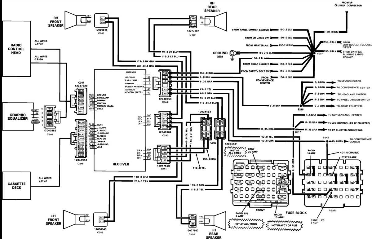
Understanding Symbols in the Wiring Diagram
Wiring diagrams use a standardized set of symbols to represent components and connections. Here's a breakdown of common symbols:
- Solid Lines: Represent wires. Thicker lines often indicate wires carrying more current.
- Dashed Lines: May represent shielded cables or connections to ground.
- Colors: Wires are color-coded for identification. Understanding the color code is crucial for tracing wires and making correct connections. For example, a wire labeled "YL/BK" would be yellow with a black stripe. The complete color key is provided in the full wiring diagram file.
- Circles with Numbers: Represent connectors. The number inside the circle typically corresponds to a pin number on the connector.
- Ground Symbol: Represents a connection to the vehicle's chassis ground. This is usually a stylized downward-pointing arrow.
- Speaker Symbol: A circle with a plus (+) and minus (-) sign. Indicates the speaker's terminals.
- Fuse Symbol: A squiggly line inside a rectangle. Protects the circuit from overcurrent.
- Resistor Symbol: A zig-zag line. Represents a component that resists the flow of current.
- Capacitor Symbol: Two parallel lines. Stores electrical energy.
Wire Color Codes: While specific codes can vary slightly across years and trims, common codes include:
- BK: Black (Ground)
- RD: Red (Power)
- WH: White
- GN: Green
- BU: Blue
- YL: Yellow
- TN: Tan
- OR: Orange
- VT: Violet
- GY: Gray
- BN: Brown
Combinations like YL/BK (Yellow with Black Stripe) are also common.
How It Works: Following the Signal Path
The 2010 Silverado stereo system operates by transmitting an audio signal from the head unit, through various components, and ultimately to the speakers.
- Signal Generation: The head unit generates the audio signal from a source like the radio, CD player, or auxiliary input.
- Pre-Amplification (If Applicable): The head unit may have a pre-amplifier stage that boosts the signal level.
- Amplification (If Applicable): If the vehicle has a factory amplifier, the signal travels from the head unit to the amplifier. The amplifier increases the signal power to drive the speakers. If no amplifier is present, the head unit directly powers the speakers.
- Signal Distribution: The amplified signal is then distributed to the individual speakers through the wiring harnesses.
- Sound Reproduction: The speakers convert the electrical signal into audible sound waves.
- Grounding: Each component, especially the head unit and amplifier, requires a solid ground connection to the vehicle's chassis. A poor ground connection can cause noise, distortion, or even component failure.
Real-World Use: Basic Troubleshooting Tips
Here are some common problems you can diagnose using the wiring diagram:
- No Power to Head Unit: Check the fuses related to the radio and accessory power. Use a multimeter to verify that power and ground are present at the head unit connector. The wiring diagram will show you the correct pins for power and ground.
- One Speaker Not Working: Trace the speaker wires from the head unit or amplifier (if applicable) to the speaker. Check for loose connections or damaged wiring. Test the speaker itself with a multimeter to verify its continuity.
- Static or Noise: Check the ground connections for all components. A poor ground can introduce noise into the system. Inspect the wiring for damage or corrosion.
- Blown Fuses: Repeatedly blown fuses indicate a short circuit. Use the wiring diagram to isolate the affected circuit and look for damaged wiring or components.
When troubleshooting, always disconnect the battery's negative terminal to prevent electrical shorts and potential damage to the system.
Safety Considerations
Working with electrical systems can be dangerous. Here are some safety precautions:
- Disconnect the Battery: Always disconnect the negative battery terminal before working on the stereo system. This prevents accidental shorts and electrical shocks.
- Work in a Well-Lit Area: Ensure you have adequate lighting to see the wiring and components clearly.
- Use Proper Tools: Use insulated tools to prevent electrical shocks.
- Identify High-Risk Components: The amplifier (if present) and the head unit contain high-current circuits. Be especially careful when working around these components.
- Avoid Working with Live Wires: Never work on the system with the ignition on or the battery connected unless absolutely necessary for testing.
- Consult a Professional: If you are uncomfortable working with electrical systems, consult a qualified automotive electrician.
The 2010 Silverado stereo wiring diagram is a valuable tool for anyone working on their truck's audio system. By understanding the symbols, components, and signal flow, you can confidently troubleshoot problems, install upgrades, and customize your audio system to your liking. Remember to prioritize safety and take your time to ensure correct connections.
We have a comprehensive, downloadable PDF of the 2010 Silverado Stereo Wiring Diagram ready for you. This file contains detailed schematics, color codes, and connector pinouts. Click [link to download the PDF here – placeholder] to access the full diagram and take your audio project to the next level. (Note: Replace the '#' with an actual link to the file.)