2010 Toyota Corolla Fuse Box Diagram
Working on your 2010 Toyota Corolla's electrical system? A fuse box diagram is your best friend. Whether you're diagnosing a faulty headlight, installing a new aftermarket component, or simply trying to understand your car's electrical architecture, this diagram is an invaluable resource. Think of it as a roadmap to your Corolla's electrical nervous system. This article will provide a detailed breakdown of the 2010 Toyota Corolla fuse box diagram, explaining its key components, symbols, and how to use it effectively.
Purpose: Why a Fuse Box Diagram Matters
The fuse box diagram serves several crucial purposes:
- Troubleshooting Electrical Issues: The primary reason is to identify which fuse controls a specific circuit. When a component fails (e.g., the radio stops working), you can quickly check the corresponding fuse based on the diagram.
- Safe Component Installation: Before adding aftermarket accessories like lights or amplifiers, understanding the existing circuits prevents overloading and potential electrical fires. The diagram helps you choose the appropriate tap-in points and fuse ratings.
- Understanding Vehicle Systems: Even if you're not facing immediate issues, studying the diagram provides a better understanding of how different systems within your Corolla are interconnected.
- Preventing Further Damage: Replacing a blown fuse with one of a higher amperage than specified can cause significant damage to wiring and components. The diagram allows you to make informed replacement decisions.
Key Specs and Main Parts
The 2010 Toyota Corolla typically has two fuse box locations:
- Interior Fuse Box: Located inside the cabin, usually under the dashboard on the driver's side. This box primarily houses fuses for interior components like the radio, interior lights, power windows, and cigarette lighter.
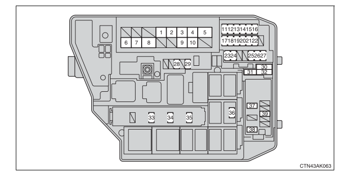
- Engine Compartment Fuse Box: Found in the engine bay, typically near the battery. This box contains fuses and relays for critical engine components like the fuel pump, ignition system, headlights, and cooling fan.
The diagram itself will usually be a printed label adhered to the inside of the fuse box cover or found in the owner's manual. It consists of a grid representing the fuse layout, with each fuse location labeled with a description of the circuit it protects and its amperage rating (e.g., "15A CIG & RADIO").
Key specs to pay attention to include:
- Fuse Amperage Rating (A): Indicates the maximum current a fuse can handle before blowing. Common ratings are 5A, 7.5A, 10A, 15A, 20A, 25A, and 30A. Never replace a fuse with one of a higher amperage, as this can create a fire hazard.
- Circuit Description: Explains what system or component the fuse protects (e.g., "Headlight (RH)", "ABS").
- Relays: While not fuses, relays are also often shown on the engine compartment fuse box diagram. Relays are electrically operated switches that control higher-current circuits.
Symbols: Lines, Colors, and Icons
Understanding the symbols used in the fuse box diagram is crucial for accurate interpretation:
- Lines: Indicate the connection of fuses to specific circuits. Different line styles can sometimes indicate different types of connections.
- Colors (on Fuses): Although the diagram itself is typically black and white, the fuses themselves are color-coded to indicate their amperage rating. This is a critical visual aid. For example:
- Yellow: 20A
- Blue: 15A
- Red: 10A
- Brown: 7.5A
- Orange: 5A
- Icons: Some diagrams use icons to represent components. Common icons include:
- Headlight symbol: Represents the headlight circuit.
- Radio symbol: Represents the radio circuit.
- Fan symbol: Represents the cooling fan circuit.
Pay close attention to any notes or legends on the diagram, as these often provide important clarifying information.
How It Works
The fuse box acts as a central distribution and protection point for your Corolla's electrical system. Each fuse protects a specific circuit from overcurrent. When the current flowing through a circuit exceeds the fuse's amperage rating, the fuse's internal element melts, breaking the circuit and preventing damage to the protected components.
Think of it like a weak link in a chain. The fuse is designed to break first, preventing more expensive components from being damaged by a short circuit or overload. When a fuse blows, it's essential to identify the cause of the overcurrent before replacing the fuse. Repeatedly blowing fuses indicates a problem that needs further investigation.
Real-World Use: Basic Troubleshooting Tips
Here's how to use the fuse box diagram for basic troubleshooting:
- Identify the Problem: Determine which component is not working. For example, the windshield wipers aren't functioning.
- Consult the Diagram: Locate the fuse box diagram (either on the fuse box cover or in your owner's manual). Find the fuse labeled for the windshield wipers.
- Inspect the Fuse: Using a fuse puller (or needle-nose pliers carefully), remove the suspected fuse. Visually inspect the fuse. A blown fuse will have a broken filament visible through the clear plastic housing.
- Test the Fuse (Optional): For a more definitive test, use a multimeter set to continuity mode. Touch the probes to each end of the fuse. A good fuse will show continuity (the multimeter will beep or display a near-zero resistance reading). A blown fuse will show no continuity.
- Replace the Fuse: Replace the blown fuse with a new fuse of the exact same amperage rating.
- Test the Component: Turn on the ignition and test the previously non-functional component. If it now works, the problem was likely a blown fuse.
- Investigate if the Fuse Blows Again: If the new fuse blows immediately or shortly after being replaced, there's a more serious underlying electrical issue that needs professional diagnosis. This could be a short circuit, a faulty component, or damaged wiring.
Safety: Highlight Risky Components
Working with electrical systems can be hazardous. Always follow these safety precautions:
- Disconnect the Battery: Before working on any electrical components, disconnect the negative (-) terminal of the battery. This prevents accidental short circuits and shocks.
- Use Appropriate Tools: Use insulated tools designed for automotive electrical work.
- Never Bypass Fuses: Never use a piece of wire or other conductive material to bypass a fuse. This is extremely dangerous and can cause a fire.
- Be Aware of High-Current Circuits: Some circuits, especially those in the engine compartment (e.g., starter motor, alternator), carry high currents. Exercise extreme caution when working around these circuits.
- Consult a Professional: If you are uncomfortable working with electrical systems or are unsure about any aspect of the repair, consult a qualified mechanic. Don't risk damaging your car or injuring yourself.
Working on your 2010 Toyota Corolla's electrical system can be manageable with the right tools and knowledge. The fuse box diagram is an essential tool in your arsenal. By understanding its layout, symbols, and how it works, you can safely and effectively troubleshoot electrical issues and maintain your vehicle's electrical health. Remember safety first and consult a professional when needed.
We have a high-resolution, downloadable version of the 2010 Toyota Corolla fuse box diagram available. Knowing the exact diagram for your specific vehicle trim level and options is critical. Contact us to request the file!