2011 Chevy Traverse Fuse Box Diagram
Alright, let's dive into the fuse box diagram for the 2011 Chevy Traverse. This might seem intimidating at first glance, but understanding it can save you a ton of time and money when troubleshooting electrical issues. Whether you're planning on adding aftermarket accessories, diagnosing a faulty circuit, or simply trying to understand your vehicle's electrical system better, a solid grasp of this diagram is essential.
Purpose of the Fuse Box Diagram
Why is this diagram so important? Well, the fuse box acts as the central protection unit for your Traverse's electrical system. Each fuse protects a specific circuit, preventing damage from overcurrent. Without them, a short circuit could lead to serious damage, even a fire. The fuse box diagram is your roadmap to identifying which fuse controls which component. It's critical for:
- Troubleshooting electrical problems: Quickly identify and replace a blown fuse.
- Adding aftermarket accessories: Ensure you're tapping into the correct circuit and using the appropriate fuse rating.
- Understanding the vehicle's electrical system: Gain a deeper understanding of how different components are powered and protected.
- Preventing further damage: Correctly identifying and addressing the cause of a blown fuse can prevent recurring issues and more significant damage.
Key Specs and Main Parts
The 2011 Chevy Traverse typically has at least two fuse boxes: one located under the hood (engine compartment) and another inside the passenger compartment, usually on the driver's side, often behind a small access panel. Some models might have a third fuse box located in the rear cargo area.
Fuse Box Locations:
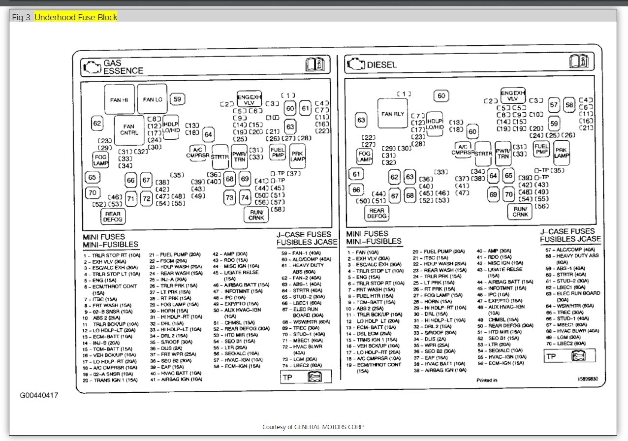
- Under-Hood Fuse Box: Contains fuses and relays for engine management, headlights, horn, cooling fans, and other high-current systems. This is where you'll typically find the larger amperage fuses.
- Passenger Compartment Fuse Box: Protects circuits for interior lights, radio, power windows, door locks, and other comfort and convenience features.
- Rear Cargo Area Fuse Box (if equipped): May contain fuses and relays related to rear-window defrost, liftgate operations, and other rear-specific systems.
Key components within each fuse box include:
- Fuses: The sacrificial elements. They contain a thin wire that melts and breaks the circuit when excessive current flows through it. Fuses are typically rated in Amperes (A), indicating the amount of current they can handle before blowing.
- Relays: Electrically operated switches. They allow a low-current circuit to control a high-current circuit. Relays are used for things like headlights, fuel pump, and starter motor, where the current draw is too high to be directly controlled by a switch.
- Bus Bars: Conductive strips that distribute power to multiple fuses or relays.
- Connectors: Provide secure connections for wiring harnesses.
Symbols and Diagram Interpretation
Understanding the symbols used in the fuse box diagram is crucial. The diagram will visually represent each fuse and relay, along with its corresponding circuit. Here's a breakdown of common symbols:
- Lines: Represent electrical wiring. Thicker lines generally indicate higher current-carrying capacity.
- Rectangles or Squares: Typically represent fuses. The number inside or next to the rectangle indicates the fuse amperage rating (e.g., "20" means a 20-amp fuse).
- Circles or Ovals: Often represent relays. The diagram might show the relay's coil and contacts.
- Ground Symbol (typically three horizontal lines decreasing in length): Indicates a connection to the vehicle's chassis ground.
- Component Symbols: Simple icons representing the components powered by the circuit (e.g., a lightbulb for headlights, a speaker for the radio).
- Color Coding: Sometimes, wiring is color-coded on the diagram to match the actual wires in the vehicle. This can be helpful for tracing circuits. Note however, wire color can change along the harness so check for the function you are troubleshooting for rather than wire color alone.
The fuse box diagram is usually organized in a grid-like fashion. Each fuse or relay is assigned a unique identifier (e.g., "F1", "R2"). The diagram will have a legend or table that lists each identifier along with the circuit it protects or controls. For example, "F1 - Headlights (Low Beam)" means that fuse F1 protects the low beam headlights.
How It Works
The electrical system in your Traverse is a closed loop. The battery provides the power, and wires conduct that power to various components. Each circuit is protected by a fuse. When excessive current flows through a circuit (due to a short circuit or overload), the fuse's internal element melts, breaking the circuit and stopping the flow of current. This prevents damage to the wiring and components connected to that circuit.
Relays act as intermediaries. A low-current signal from a switch (e.g., the headlight switch) activates the relay, which then closes a high-current circuit to power the headlights. This protects the switch from having to handle the full current required by the headlights.
Real-World Use: Basic Troubleshooting Tips
Here's how to use the fuse box diagram for basic troubleshooting:
- Identify the Problem: Determine which component is not working (e.g., the radio, the power windows).
- Consult the Diagram: Locate the fuse box diagram (usually in your owner's manual or downloadable online – see below). Find the fuse or relay associated with the malfunctioning component.
- Inspect the Fuse: Visually inspect the fuse. Look for a broken filament inside the fuse. A blown fuse will have a gap in the wire.
- Test the Fuse (Optional): Use a multimeter to test the fuse for continuity. Set the multimeter to the continuity setting (usually indicated by a sound wave symbol). Touch the probes to both ends of the fuse. If the multimeter beeps or shows a reading of near zero ohms, the fuse is good. If there's no continuity, the fuse is blown.
- Replace the Fuse: Replace the blown fuse with a new fuse of the same amperage rating. Never use a fuse with a higher amperage rating, as this can damage the circuit.
- Test the Component: After replacing the fuse, test the component to see if it's working again.
- If the Fuse Blows Again: If the new fuse blows immediately or shortly after being replaced, there's likely a short circuit or overload in the circuit. Further diagnosis is required to find and repair the underlying problem. This may involve checking wiring for damage, testing components for shorts, or consulting a qualified mechanic.
Safety Precautions
Working with electrical systems can be dangerous. Here are some safety precautions:
- Disconnect the Battery: Before working on any electrical system, disconnect the negative (-) battery cable to prevent accidental shorts or shocks.
- Use Proper Tools: Use insulated tools to prevent electrical shock.
- Avoid Water: Never work on electrical systems in wet conditions.
- Be Careful with High-Current Circuits: Components like the starter motor, alternator, and battery cables carry high currents and can be dangerous if shorted.
- Do Not Modify Fuses: Never bypass a fuse or use a fuse with a higher amperage rating than specified. This can create a fire hazard.
Specifically, be cautious around the under-hood fuse box, as it contains circuits directly connected to the battery and high-power components like the alternator and starter. Accidental shorts in this area can cause significant damage or injury.
Remember, if you're not comfortable working on electrical systems, it's always best to consult a qualified mechanic.
We have the full, high-resolution 2011 Chevy Traverse Fuse Box Diagram file available for download. This comprehensive diagram will give you all the detail you need to accurately diagnose electrical issues in your vehicle. Happy wrenching!