2011 Dodge Ram 1500 Rear Suspension Diagram
Alright, let's dive into the rear suspension of the 2011 Dodge Ram 1500. Understanding this system is crucial whether you're planning a lift, troubleshooting a clunking noise, or just expanding your automotive knowledge. We're going to break down the diagram in a way that's both technically accurate and easy to grasp. This isn't just about memorizing parts; it's about understanding how they all work together.
Purpose of Understanding the Diagram
Why bother with a rear suspension diagram? Several reasons. First, it's invaluable for repairs. Identifying components quickly and knowing how they connect saves time and prevents mistakes. Second, it's essential for modification. Planning a lift kit, upgrading shocks, or replacing springs requires a clear understanding of the existing setup. Finally, it's simply about knowledge. The more you understand your vehicle, the better equipped you are to maintain it and spot potential problems early.
Key Specs and Main Parts
The 2011 Dodge Ram 1500 utilizes a solid rear axle suspension system, specifically a five-link coil spring design. This setup offers a good balance between ride comfort, load-carrying capacity, and durability. Here are the main components:
- Solid Rear Axle: The backbone of the system. It transmits power from the driveshaft to the wheels and provides a rigid structure for the suspension components to attach to.
- Coil Springs: These provide the primary suspension, absorbing bumps and maintaining ride height. The spring rate (measured in lbs/inch or N/mm) determines how stiff the suspension is. Higher spring rates support heavier loads but result in a firmer ride.
- Shock Absorbers (Dampers): Control the oscillations of the springs, preventing the truck from bouncing excessively. They convert kinetic energy into heat through hydraulic resistance. Types include twin-tube, monotube, and gas-charged.
- Upper Control Arms (Upper Links): Two upper control arms on each side help locate the axle laterally and control axle movement.
- Lower Control Arms (Lower Links): Two lower control arms on each side, typically longer than the uppers, primarily control fore-aft axle movement and contribute to axle location.
- Track Bar (Panhard Rod): A lateral bar that prevents side-to-side movement of the axle. It's crucial for maintaining proper vehicle stability.
- Bump Stops: These prevent the suspension from bottoming out, protecting the shocks and other components from damage during extreme compression.
- Axle Housing: The protective shell that encloses the differential and axle shafts.
- Differential: The component that allows the wheels to rotate at different speeds, essential for turning. Could be an open differential, limited-slip differential (LSD), or locking differential.
Diagram Symbols Explained
Understanding the symbols in the diagram is essential. Here's a breakdown of common conventions:
- Solid Lines: Typically represent physical components like control arms, the axle housing, or the frame.
- Dashed Lines: Often indicate hidden components or lines of force/motion. For instance, a dashed line might show the path of axle movement.
- Circles: Usually denote pivot points or mounting locations, like where a control arm attaches to the frame or axle.
- Arrows: Illustrate the direction of movement or force. For example, an arrow pointing upwards on a spring indicates its resistance to compression.
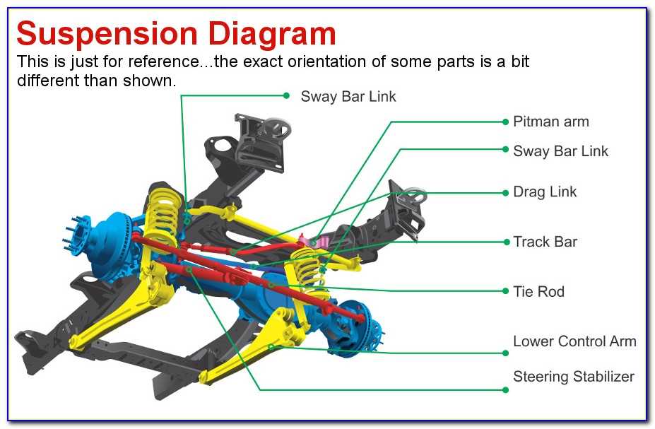
- Color Coding (If Present): Some diagrams use color to differentiate between systems or components. For example, one color might represent brake lines, while another represents suspension parts. The legend will explain.
- Numbers/Letters: These correspond to a parts list or legend, allowing you to identify specific components by their designation.
It's important to cross-reference the diagram with the accompanying parts list to ensure you're identifying each component correctly. Look for details like torque specifications, part numbers, and any special installation instructions.
How the Rear Suspension Works
The 2011 Ram 1500's rear suspension operates as follows:
- When the wheels encounter a bump, the coil springs compress, absorbing the initial shock.
- The shock absorbers dampen the spring's oscillations, preventing excessive bouncing and maintaining ride control.
- The control arms (both upper and lower) work together to control the axle's movement. The lower control arms primarily handle fore-aft movement, while the upper control arms assist in lateral location and axle stability during articulation.
- The track bar prevents lateral movement of the axle, ensuring the vehicle tracks straight.
- The bump stops prevent the suspension from bottoming out during severe impacts, protecting the shocks and other components.
The five-link system provides a controlled and predictable axle movement, which contributes to good handling and stability, both on and off-road. The coil springs offer a more compliant ride compared to traditional leaf springs, especially when the truck is unloaded.
Real-World Use: Basic Troubleshooting
Here are a few common rear suspension issues and how the diagram can help:
- Clunking Noise: Could be worn-out bushings in the control arms, a loose track bar, or damaged shocks. The diagram helps you pinpoint the location of each component and inspect it for wear or damage.
- Excessive Bouncing: Usually indicates worn-out shock absorbers. The diagram shows you how to access and replace the shocks.
- Rear End Sagging: Could be caused by worn-out coil springs or overloaded cargo. The diagram helps you identify the springs and determine if they need to be replaced.
- Vehicle Drifting or Pulling to One Side: Might indicate a bent axle, damaged control arms, or a misaligned track bar. The diagram helps you visualize the alignment of the components and identify any potential damage.
Before diving into any repairs, always consult the service manual for specific torque specifications and procedures.
Safety Considerations
Safety is paramount when working on suspension components. Here are some critical points:
- Spring Compression: Coil springs store a significant amount of energy. Compressing or decompressing them incorrectly can be extremely dangerous. Use proper spring compressors and follow all safety instructions.
- Jacking and Support: Always use jack stands to support the vehicle securely before working underneath it. Never rely solely on a jack.
- Brake Lines: Be careful not to damage brake lines while working on the suspension. A leak in the brake system can be catastrophic.
- Wheel Alignment: After making significant suspension changes, such as replacing control arms or adjusting ride height, it's essential to get a professional wheel alignment.
- Torque Specifications: Always tighten bolts and nuts to the specified torque values. Under-tightening can lead to loosening and failure, while over-tightening can damage the components.
Working on suspension components can be physically demanding and requires specialized tools. If you're not comfortable with any aspect of the repair, it's best to consult a qualified mechanic.
By understanding the diagram and the principles of the 2011 Dodge Ram 1500 rear suspension, you'll be better equipped to diagnose problems, perform repairs, and even make modifications with confidence. Remember to always prioritize safety and consult the service manual for specific instructions.
We have the full, high-resolution diagram available. You can download it for a more detailed look and to assist with your projects.