
2011 F250 4x4 Front Suspension Diagram
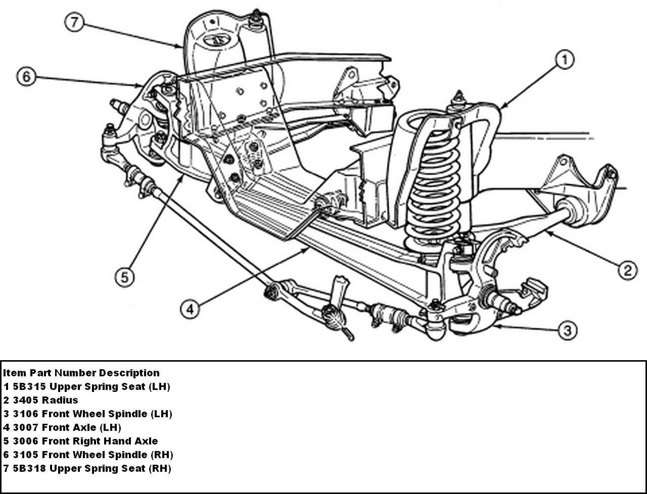
If you're diving into the front suspension of your 2011 Ford F250 4x4, having a solid understanding of its components and how they work together is crucial. This article serves as a guide to deciphering a typical front suspension diagram, explaining the key parts, their function, and offering some practical troubleshooting advice. We'll approach this like a seasoned mechanic explaining things clearly to a DIY enthusiast.
Purpose of the Diagram
Why bother with a front suspension diagram? Several reasons:
- Repair and Maintenance: Diagnosing and fixing suspension issues becomes significantly easier. A visual representation helps you pinpoint the faulty component faster.
- Modification and Upgrades: Planning a lift kit, leveling kit, or even replacing worn-out parts requires a solid understanding of the existing setup. A diagram helps ensure compatibility.
- Learning and Understanding: Even if you're not planning immediate work, understanding how the suspension works enhances your overall automotive knowledge.
- Avoiding Mistakes: Improperly reassembling suspension components can be dangerous. A diagram serves as a reference to ensure everything goes back together correctly.
Key Specs and Main Parts of the 2011 F250 4x4 Front Suspension
The 2011 F250 4x4 typically utilizes a solid front axle design, often referred to as a beam axle. This is a robust setup designed for heavy-duty applications and off-road capability. Here's a breakdown of the key components:
- Solid Front Axle: A rigid beam connecting the front wheels. It provides strength and durability, essential for handling heavy loads and challenging terrain.
- Coil Springs: Located between the axle and the frame, coil springs provide the primary suspension by absorbing bumps and road irregularities. Spring rate is crucial; it determines the stiffness of the suspension.
- Shock Absorbers (Dampers): These control the oscillations of the coil springs, preventing the vehicle from bouncing excessively. A worn shock absorber leads to a bouncy and unstable ride.
- Radius Arms: These arms connect the axle to the frame and control axle movement, particularly during acceleration and braking. They help maintain proper axle alignment.
- Radius Arm Brackets: These are the mounting points on the frame where the radius arms attach. Inspect these for cracks or damage.
- Track Bar (Panhard Rod): This bar connects the axle to the frame and prevents lateral movement of the axle. It's crucial for maintaining proper vehicle tracking.
- Track Bar Bracket: The mounting point for the track bar on the frame.
- Steering Linkage: This system transmits steering input from the steering wheel to the front wheels. It includes components like the drag link, tie rods, and steering stabilizer.
- Leaf Springs (Some models): While less common, some 2011 F250 configurations might utilize leaf springs in the front. Leaf springs provide both suspension and axle location.
- U-Bolts (If Leaf Springs are present): These secure the leaf springs to the axle. They should be tightened to the manufacturer's specifications.
- Sway Bar (Anti-Roll Bar): This bar connects the left and right sides of the suspension and helps reduce body roll during cornering. The sway bar links connect the sway bar to the axle.
- Bushings: Found at various pivot points, bushings absorb vibrations and allow for controlled movement. Worn bushings contribute to noise and poor handling.
- Ball Joints: Although this suspension utilizes a solid axle, ball joints may still exist within the steering knuckles for steering.
Understanding Diagram Symbols
Suspension diagrams use a variety of symbols to represent different components and connections. Here’s a general guide:
- Solid Lines: Typically represent rigid components like the axle, radius arms, and track bar. Thicker lines may indicate a larger or stronger component.
- Dashed Lines: Often indicate hidden lines, lines that are behind other components, or lines indicating movement.
- Circles: Can represent bolts, bushings, or pivot points. A filled circle typically indicates a fixed connection, while an open circle might represent a rotating joint.
- Spring Symbol (Coil or Leaf): A coiled line represents a coil spring. A series of stacked curved lines represents a leaf spring.
- Shock Absorber Symbol: Usually a vertical line with a zig-zag pattern through it.
- Arrows: Indicate the direction of movement or force.
- Abbreviations: Look for abbreviations like "RH" (right hand), "LH" (left hand), "FT" (foot), "IN" (inch), and "Nm" (Newton-meter – a unit of torque).
Color coding, if present, often highlights different systems or materials. A legend accompanying the diagram should explain any specific color scheme used.
How It Works: A Simplified Explanation
Here's a simplified overview of how the 2011 F250 4x4 front suspension operates:
- Impact Absorption: When the wheels encounter a bump, the coil springs (or leaf springs) compress, absorbing the initial impact energy.
- Dampening Oscillations: The shock absorbers dampen the spring's oscillations, preventing the vehicle from bouncing uncontrollably.
- Axle Control: The radius arms (or leaf springs) control the fore-aft movement of the axle, maintaining proper alignment and preventing axle wrap (rotation of the axle housing under acceleration).
- Lateral Stability: The track bar prevents the axle from moving side-to-side, ensuring stable handling.
- Steering: When the steering wheel is turned, the steering linkage transmits the motion to the steering knuckles, causing the wheels to turn.
- Sway Control: The sway bar resists body roll during cornering, improving stability and handling.
Real-World Use: Basic Troubleshooting Tips
Here are a few common suspension problems and how a diagram can assist in diagnosis:
- Clunking Noise: Often caused by worn bushings, loose bolts, or a failing shock absorber. The diagram helps you identify the potential sources of the noise.
- Bouncing Ride: Usually indicates worn shock absorbers. The diagram confirms the location and mounting of the shocks.
- Poor Handling: Can be caused by worn bushings, loose steering linkage components, or a bent track bar. The diagram helps you inspect the condition and alignment of these parts.
- Uneven Tire Wear: May indicate misaligned components, such as a bent axle or worn ball joints (if applicable). The diagram provides a reference for checking alignment.
- Steering Wander: Can be caused by worn tie rod ends, or loose track bar. Diagram assists you in locating and identifying each of these parts.
Always consult the manufacturer's service manual for specific troubleshooting procedures and torque specifications.
Safety First!
Working on suspension components can be dangerous due to the potential energy stored in the springs. Always take these precautions:
- Use Jack Stands: Never work under a vehicle supported only by a jack.
- Compress Springs Carefully: If you need to remove coil springs, use a spring compressor and follow the manufacturer's instructions precisely. Improper use can lead to serious injury.
- Loosen and Tighten Bolts Gradually: Avoid loosening or tightening bolts abruptly, as this can cause components to shift unexpectedly.
- Wear Safety Glasses: Protect your eyes from debris.
- Refer to the Service Manual: Torque specifications are critical. Overtightening can damage components, while undertightening can lead to failure.
- The radius arms are extremely heavy and difficult to maneuver.
Working on suspension components requires specialized tools and knowledge. If you're not comfortable with any aspect of the repair, it's best to consult a qualified mechanic.
We have a basic schematic diagram of the 2011 F250 4x4 front suspension available. You can download it to supplement this guide. However, remember that specific configurations may vary, so always verify information against your vehicle's actual setup and consult the factory service manual for complete and accurate information.