
2011 F250 Upfitter Switch Wiring Diagram
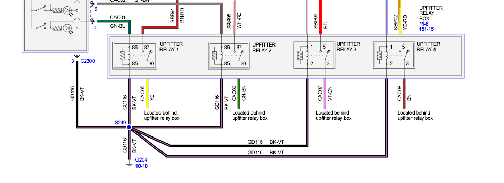
If you own a 2011 Ford F-250, chances are you're putting it to work. And if you're putting it to work, you've probably considered adding aftermarket accessories – lights, winches, plows, you name it. That's where the upfitter switches come in handy. These factory-installed switches provide a convenient and clean way to power your accessories without splicing into factory wiring, which can lead to electrical problems down the road. Understanding the 2011 F-250 upfitter switch wiring diagram is crucial for safe and effective installation and troubleshooting. This article will guide you through the intricacies of that diagram, explaining its symbols, functions, and practical applications.
Purpose of Understanding the Upfitter Switch Wiring Diagram
Why bother learning about the wiring diagram? Several reasons:
- Safe Accessory Installation: Connecting accessories without understanding the wiring can overload circuits, damage components, or even cause a fire. The diagram helps you identify the correct wires and connections.
- Troubleshooting Electrical Issues: If your accessories aren't working or the upfitter switches are malfunctioning, the diagram is essential for diagnosing the problem and pinpointing the source of the fault.
- Modification and Customization: Perhaps you want to change the functionality of the switches, such as adding a relay for a higher amperage accessory. The diagram provides the knowledge needed to modify the system safely and effectively.
- Learning and Expanding Knowledge: Even if you don't plan to work on the wiring yourself, understanding the diagram gives you a deeper understanding of your vehicle's electrical system, making you a more informed owner.
Key Specs and Main Parts
The 2011 F-250 typically comes with four upfitter switches located on the overhead console. Here's a breakdown of the key specifications and components involved:
- Upfitter Switches: These are the user-controlled switches themselves. They provide the on/off control for the circuits.
- Relays: Each upfitter switch controls a relay. A relay is an electrically operated switch that allows a low-current circuit (the upfitter switch) to control a high-current circuit (the accessory). This protects the switches from being overloaded.
- Fuses: Each upfitter switch circuit is protected by a dedicated fuse located in the power distribution box (fuse box) under the hood. The amperage rating of these fuses varies.
- Wiring Harness: A dedicated wiring harness runs from the upfitter switches to a blunt-cut wiring bundle located under the hood, typically near the passenger side firewall. This bundle is where you connect your accessories.
- Ground Point: A dedicated ground point is essential for completing the circuits. Ensure you have a solid ground connection for your accessories.
The amperage rating of each switch circuit is a critical spec. Typically, the switches are rated as follows (but *always* verify with your vehicle's specific documentation):
- Switch 1 & 2: 30 Amps
- Switch 3 & 4: 10 Amps
Exceeding these amperage ratings can damage the relays and fuses, potentially leading to a fire.
Decoding the Wiring Diagram: Symbols and Conventions
Wiring diagrams use standardized symbols to represent electrical components and connections. Here's a guide to interpreting the symbols you'll encounter in the 2011 F-250 upfitter switch wiring diagram:
- Solid Lines: Represent wires. The thickness of the line might indicate the wire gauge (size).
- Dashed Lines: Can represent shielding, or wires contained in a harness together.
- Circles: Can represent connection points or splices. A filled circle typically means a direct connection.
- Rectangles with SW inside: Represents a switch.
- Coil Symbol: Represents a relay coil.
- F inside a Box Symbol: Represents a fuse.
- Ground Symbol (usually a series of descending lines): Indicates a connection to the vehicle's chassis ground.
- Color Codes: Wires are often identified by color codes, such as BK (Black), RD (Red), WH (White), GN (Green), BU (Blue), YE (Yellow), BN (Brown), OR (Orange). These codes are essential for identifying the correct wires.
The wiring diagram will also show the pin numbers on connectors and relays, which are crucial for making the correct connections. Pay close attention to these pin numbers.
How It Works: A Circuit's Journey
Let's trace the path of electricity through a typical upfitter switch circuit:
- When you flip an upfitter switch ON, it sends a small amount of current from the truck's battery, through the switch, to the corresponding relay's coil.
- This current energizes the relay coil, creating an electromagnetic field.
- The electromagnetic field pulls the relay's internal switch closed.
- This closed switch allows a higher current to flow directly from the truck's battery (through the fuse for that switch) to the blunt-cut wire in the engine compartment designated for that specific switch.
- You connect your accessory to this blunt-cut wire and to a suitable ground.
- When you turn the upfitter switch OFF, the relay coil de-energizes, the relay's internal switch opens, and the current to your accessory is cut off.
This system allows the low-current upfitter switches to safely control high-current accessories.
Real-World Use: Basic Troubleshooting Tips
Here are some common troubleshooting scenarios and how the wiring diagram can help:
- Accessory Not Working:
- Check the fuse for that specific upfitter switch. A blown fuse is a common cause. Use the diagram to locate the correct fuse.
- Verify the ground connection for your accessory. A poor ground is a frequent culprit.
- Test the voltage at the blunt-cut wire in the engine compartment when the switch is ON. If there's no voltage, the relay may be faulty. The diagram helps you trace the wiring back to the relay.
- Use a multimeter to check the continuity of the wiring between the switch, relay, and accessory. A break in the wire can prevent current flow.
- Upfitter Switch Not Working:
- Check the fuse for that switch.
- Test the switch itself for continuity when in the ON position. If there's no continuity, the switch is likely faulty.
- Inspect the wiring harness for any signs of damage or corrosion.
Important: Before performing any electrical troubleshooting, disconnect the negative battery cable to prevent accidental short circuits and electrical shock.
Safety: Highlight Risky Components
Working with electrical systems can be dangerous. Here are some key safety considerations:
- Battery: The truck's battery can deliver a massive amount of current, which can cause severe burns and electrical shock. Always disconnect the negative battery cable before working on the electrical system.
- Fuses: Never replace a fuse with one of a higher amperage rating. This can overload the circuit and cause a fire.
- Relays: Be careful when testing relays. Ensure you are using the correct voltage and polarity. Incorrect connections can damage the relay or other components.
- Wiring: Avoid cutting or splicing into factory wiring unless absolutely necessary. If you must, use proper crimping tools and connectors to ensure a secure and reliable connection. Always insulate splices properly to prevent short circuits.
- High-Amperage Accessories: Accessories like winches and high-powered lights draw a significant amount of current. Ensure the wiring and components are rated to handle the load. Consider using heavier gauge wire and higher amperage relays for these accessories.
Always wear appropriate safety gear, such as safety glasses and gloves, when working on electrical systems.
We have access to the 2011 Ford F-250 Upfitter Switch Wiring Diagram. You can download the diagram from this location [Placeholder for Diagram Download Link]. Remember to consult your vehicle's specific service manual for the most accurate and up-to-date information.
By understanding the 2011 F-250 upfitter switch wiring diagram, you can safely and effectively install and troubleshoot accessories, enhancing the functionality and versatility of your truck.