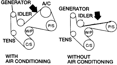
2011 Ford Explorer Serpentine Belt Diagram
The serpentine belt in your 2011 Ford Explorer is a critical component responsible for powering several essential engine accessories. This article provides a detailed look at the serpentine belt diagram for your vehicle, explaining its purpose, components, functionality, and how to use it for maintenance and troubleshooting. Having a clear understanding of this system can save you money on repairs and help you keep your Explorer running smoothly.
Purpose of the Serpentine Belt Diagram
The serpentine belt diagram serves as a visual guide to the routing of the serpentine belt around various engine pulleys. This diagram is invaluable for several reasons:
- Replacement: When replacing a worn or broken serpentine belt, the diagram ensures you route the new belt correctly. Incorrect routing can lead to component failure and engine damage.
- Troubleshooting: The diagram helps identify the specific accessories powered by the belt, allowing you to diagnose issues such as a failing alternator, power steering pump, or air conditioning compressor.
- Maintenance: Regularly inspecting the belt and pulleys becomes easier with a clear understanding of the system's layout.
- Learning: For those interested in automotive mechanics, studying the diagram provides insight into how engine accessories are driven.
Key Specs and Main Parts (2011 Ford Explorer)
The 2011 Ford Explorer came with a few different engine options, and the serpentine belt routing may vary slightly depending on the engine. The most common engines are:
- 3.5L V6 (Ti-VCT): This is the most common engine. The serpentine belt typically drives the alternator, power steering pump, air conditioning compressor, water pump, and idler pulley.
- 2.0L I4 (EcoBoost): This engine uses a slightly different serpentine belt arrangement, usually driving the alternator, water pump, and AC compressor.
Regardless of the engine, the key components involved in the serpentine belt system include:
- Serpentine Belt: A long, continuous belt made of reinforced rubber that transmits power from the crankshaft pulley to the other accessory pulleys.
- Crankshaft Pulley (Harmonic Balancer): The main pulley driven directly by the engine's crankshaft. This is the source of power for the entire serpentine belt system.
- Alternator Pulley: Powers the alternator to charge the battery and provide electrical power to the vehicle.
- Power Steering Pump Pulley: Drives the power steering pump to provide hydraulic assistance for steering.
- Air Conditioning Compressor Pulley: Powers the air conditioning compressor, which circulates refrigerant to cool the cabin.
- Water Pump Pulley: Drives the water pump, which circulates coolant through the engine to prevent overheating.
- Tensioner Pulley: A spring-loaded pulley that maintains the proper tension on the serpentine belt. This is crucial for preventing slippage and ensuring efficient power transfer.
- Idler Pulley: A smooth pulley that guides the belt around the engine components and helps maintain the correct wrap angle on other pulleys.
Key Specs: The serpentine belt length and width are crucial specifications. Using the wrong belt can lead to improper tension and premature failure. Refer to your vehicle's owner's manual or a reputable auto parts store to determine the correct belt size for your specific engine. These measurements are usually listed in millimeters and can be found on the old belt itself or in online catalogs.
Understanding Serpentine Belt Diagram Symbols
Serpentine belt diagrams use a standardized set of symbols to represent the various components and belt routing. Here's a breakdown of common symbols:
- Solid Lines: Represent the serpentine belt itself. The path of the line indicates how the belt is routed around the pulleys.
- Pulleys: Represented as circles. Labels inside or near the circles indicate the component the pulley belongs to (e.g., ALT for alternator, P/S for power steering).
- Arrows: Indicate the direction of belt rotation. This is important for understanding how each component is driven.
- Tensioner: Often depicted with a symbol indicating its spring-loaded mechanism. The tensioner symbol may also include an arrow showing the direction of its movement.
- Smooth Pulleys: Usually represent idler pulleys and the back side of components.
- Grooved Pulleys: Usually represent the crankshaft pulley, alternator, AC compressor, and power steering pump.
Color-coding is not standardized across all diagrams, but some may use colors to highlight specific sections of the belt or different accessory drives. Always refer to the legend on the diagram itself to understand the meaning of any colors used.
How the Serpentine Belt System Works
The serpentine belt system operates on a simple principle: transferring rotational power from the engine's crankshaft to various accessories. Here's a step-by-step explanation:
- The engine's crankshaft rotates, turning the crankshaft pulley.
- The serpentine belt, wrapped tightly around the crankshaft pulley, is driven by its rotation.
- As the serpentine belt moves, it turns the pulleys of the various engine accessories (alternator, power steering pump, AC compressor, water pump).
- Each accessory pulley is connected to its respective component, causing it to operate. For example, the alternator pulley spins the alternator, generating electricity.
- The tensioner pulley maintains constant tension on the belt, ensuring that it doesn't slip and that all accessories receive adequate power. Without proper tension, the belt can slip, causing reduced performance or failure of the accessories.
Real-World Use: Basic Troubleshooting
Understanding the serpentine belt diagram can greatly assist in troubleshooting issues related to the serpentine belt system. Here are some common problems and how the diagram can help:
- Squealing Noise: A squealing noise, especially when starting the engine or turning the steering wheel, often indicates a slipping serpentine belt. Use the diagram to inspect the belt for wear, cracks, or glazing. Check the tensioner pulley for proper function. A worn tensioner can cause the belt to lose tension and slip.
- Accessory Failure: If an accessory stops working (e.g., the AC blows warm air), use the diagram to confirm that the serpentine belt drives the corresponding pulley. If the belt is intact and properly routed, the issue may lie within the accessory itself.
- Belt Breakage: If the serpentine belt breaks, use the diagram to identify the correct routing path for the new belt. Ensure all pulleys are in good condition and rotate freely before installing the new belt. Check for any signs of misalignment, which can cause premature belt wear and breakage.
- Visual Inspection: Regularly inspect the belt for cracks, fraying, or missing chunks. A belt showing signs of significant wear should be replaced preventatively. Also, examine the pulleys for damage or excessive wear. A damaged pulley can damage the belt.
Important Note: Before replacing the serpentine belt, always check the condition of all pulleys. A seized or damaged pulley can quickly destroy a new belt.
Safety Considerations
Working on the serpentine belt system involves working near a running engine and potentially moving parts. Take the following safety precautions:
- Disconnect the Battery: Disconnect the negative battery terminal before working on the serpentine belt system to prevent accidental electrical shocks.
- Engine Cool Down: Allow the engine to cool down completely before working near the belt or pulleys. Exhaust manifolds and other engine components can be extremely hot.
- Moving Parts: Never put your hands or tools near the serpentine belt or pulleys while the engine is running. The belt can move at high speeds and cause serious injury.
- Eye Protection: Wear safety glasses to protect your eyes from debris.
- Proper Tools: Use the correct tools for the job, including a serpentine belt tool for releasing the tensioner. Improper tools can damage components or cause injury.
- Fan Danger: Be extremely careful around the engine cooling fan. It can start unexpectedly, even with the engine off. It is best to disable the fan motor if possible while working in that area.
The serpentine belt tensioner stores a significant amount of energy. Use caution when releasing the tension, and always use the appropriate tool to control the movement of the tensioner arm.
By understanding the serpentine belt diagram and following proper safety procedures, you can confidently maintain and troubleshoot this essential system in your 2011 Ford Explorer. Remember to consult your vehicle's service manual for specific instructions and torque specifications.
We have a high-resolution serpentine belt diagram specifically for the 2011 Ford Explorer available for download. Please [link to download]. This diagram will provide you with the detailed visual information you need for accurate belt routing and component identification.