
2011 Ford F150 Exhaust System Diagram
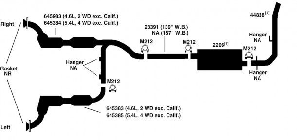
Whether you're tackling a rusty muffler, dreaming of a performance upgrade, or simply curious about what's under your 2011 Ford F-150, understanding its exhaust system is crucial. This article will serve as a comprehensive guide to the 2011 Ford F-150 exhaust system diagram, helping you navigate its intricacies and perform basic troubleshooting. Having a grasp of this system empowers you to diagnose issues, plan modifications, and execute repairs with confidence.
Purpose of Understanding the Exhaust System
Why bother diving into the exhaust system diagram? Several compelling reasons exist:
- Repair and Maintenance: Identifying components for replacement or repair is greatly simplified with a clear diagram. Knowing the exact location and function of each part speeds up the process and reduces the risk of mistakes.
- Performance Upgrades: If you're considering installing a cat-back exhaust, headers, or a performance muffler, understanding the existing system's layout is paramount. This knowledge allows you to make informed decisions about compatibility and potential performance gains.
- Troubleshooting: Unusual noises, reduced fuel economy, or failing emissions tests can often be traced back to the exhaust system. A diagram assists in pinpointing the source of the problem.
- Learning and General Knowledge: For the mechanically inclined, understanding how various systems operate within your vehicle is simply fascinating. Knowing the flow of exhaust gases from the engine to the tailpipe is valuable knowledge.
- Compliance: Modifying your exhaust system may affect emissions. It is wise to understand the parts that you may or may not alter.
Key Specs and Main Parts of the 2011 F-150 Exhaust System
The specific components and configuration of the exhaust system will vary slightly depending on your 2011 F-150's engine (3.7L V6, 5.0L V8, 6.2L V8, or 3.5L EcoBoost V6) and cab configuration (Regular Cab, SuperCab, SuperCrew). However, the fundamental components remain consistent:
Essential Components:
- Exhaust Manifolds/Headers: These components are bolted directly to the engine's cylinder heads. Their primary function is to collect exhaust gases from each cylinder and channel them into the exhaust system. Headers are often used as a performance upgrade, providing less restrictive flow compared to stock exhaust manifolds.
- Catalytic Converters: These are crucial emission control devices. They use a chemical process to convert harmful pollutants (hydrocarbons, carbon monoxide, and nitrogen oxides) into less harmful substances (water, carbon dioxide, and nitrogen).
- Oxygen Sensors (O2 Sensors): Located before and after the catalytic converters, O2 sensors monitor the oxygen content in the exhaust gas. This information is relayed to the engine control unit (ECU) or powertrain control module (PCM), which uses it to fine-tune the air-fuel mixture for optimal combustion and emissions control.
- Muffler: The muffler is designed to reduce noise produced by the exhaust gases. It achieves this through a series of chambers and baffles that dampen sound waves.
- Resonator: Often positioned before the muffler, a resonator further reduces specific frequencies of noise, contributing to a more refined exhaust note. Not all F-150s will have a resonator.
- Tailpipe: The final section of the exhaust system, the tailpipe vents the exhaust gases into the atmosphere, away from the vehicle's occupants.
- Exhaust Pipes: These are the various connecting pipes that link all the aforementioned components together. They must be properly sized and sealed to ensure efficient exhaust flow and prevent leaks.
- Hangers and Brackets: These rubber and metal supports secure the exhaust system to the vehicle's frame. They absorb vibrations and prevent the system from rattling or sagging.
- Gaskets and Flanges: These components create a seal between exhaust components to prevent leaks. They are essential for proper system performance.
Understanding Diagram Symbols
Exhaust system diagrams typically use a combination of lines, symbols, and colors to represent different components and their connections. Here's a breakdown of common symbols:
- Solid Lines: Typically represent the exhaust pipes themselves, indicating the physical path of the exhaust gas flow.
- Dashed Lines: May represent control lines (vacuum or electrical) connected to components like oxygen sensors or exhaust valves.
- Component Symbols: Each component (catalytic converter, muffler, resonator, etc.) will have a distinct symbol. These symbols can vary, but they are usually easily recognizable based on the component's shape and function. Reference the legend of the specific diagram you're using.
- Arrows: Indicate the direction of exhaust gas flow. This is crucial for understanding the system's operation.
- Color Coding: While not always present, some diagrams use colors to differentiate between different materials or types of exhaust gas (e.g., pre-catalytic converter vs. post-catalytic converter exhaust).
How the Exhaust System Works
The exhaust system's primary function is to safely and efficiently remove exhaust gases from the engine, reducing emissions and noise. The process begins with the combustion of air and fuel inside the engine's cylinders. This process creates high-pressure, high-temperature exhaust gases. These gases are then expelled through the exhaust valves and into the exhaust manifolds or headers.
From the manifolds, the exhaust gases flow into the catalytic converters, where harmful pollutants are converted into less harmful substances. The oxygen sensors, positioned before and after the catalytic converters, provide feedback to the ECU/PCM, allowing it to optimize the air-fuel mixture for efficient catalytic conversion and overall engine performance.
Next, the exhaust gases pass through the muffler and resonator (if equipped), where sound waves are dampened, reducing exhaust noise. Finally, the gases are expelled through the tailpipe into the atmosphere.
Real-World Use and Troubleshooting Tips
Here are some common exhaust system issues and how a diagram can help you troubleshoot them:
- Exhaust Leaks: Leaks can occur at any point in the system, often at joints, flanges, or where the exhaust pipe is rusted. Use the diagram to visually inspect these areas for signs of damage or corrosion. A hissing or roaring sound is a common symptom.
- Catalytic Converter Failure: A failing catalytic converter can cause reduced engine performance, poor fuel economy, and a failing emissions test. The diagram helps you locate the catalytic converter and its associated oxygen sensors, allowing you to test their functionality.
- Muffler Damage: A damaged muffler can result in excessive noise or even a rattling sound. The diagram helps you visually inspect the muffler for rust, holes, or physical damage.
- Oxygen Sensor Issues: Faulty oxygen sensors can trigger a check engine light and affect engine performance. The diagram shows the location of each oxygen sensor, making it easier to access and test them. Using an OBD-II scanner, you can use the diagram to determine which O2 sensor is reporting a problem.
- Broken Hangers: Broken or missing exhaust hangers can cause the exhaust system to sag, leading to rattling or even damage to other components. The diagram helps you identify the location and type of hangers needed for replacement.
Safety Considerations
Working on the exhaust system involves several potential hazards. It's critical to prioritize safety:
- Heat: The exhaust system gets extremely hot. Never work on the exhaust system immediately after the engine has been running. Allow ample time for it to cool down completely to prevent burns.
- Jack Stands: Always use jack stands to support the vehicle securely before working underneath it. Never rely solely on a jack.
- Eye Protection: Wear safety glasses to protect your eyes from debris and rust particles.
- Gloves: Wear gloves to protect your hands from sharp edges, rust, and potentially harmful substances.
- Carbon Monoxide: Never run the engine in an enclosed space, as this can lead to carbon monoxide poisoning. Work in a well-ventilated area.
- Penetrating Oil: Use penetrating oil on rusty bolts and fasteners to make them easier to remove. Be patient and avoid forcing them, as this can lead to breakage.
The catalytic converter contains precious metals and can be a target for theft. Ensure your vehicle is parked in a secure location.
Understanding your 2011 Ford F-150's exhaust system is a valuable asset for any DIY mechanic or enthusiast. Armed with this knowledge, you can confidently tackle repairs, upgrades, and troubleshooting tasks.
We have a high-resolution version of the 2011 Ford F-150 Exhaust System Diagram available for download. This file provides a more detailed view of the components and their layout. Contact us for access to the file.