2011 Ford F150 Fuse Box Diagram Passenger Side
Alright, let's dive into the 2011 Ford F150 passenger side fuse box diagram. Knowing your way around this diagram is crucial for everything from diagnosing a simple blown fuse to installing aftermarket accessories. Whether you're a seasoned DIYer or just starting to get your hands dirty, understanding this system will save you time, money, and potential headaches.
Purpose of the Fuse Box Diagram
Why should you even bother with this diagram? The answer is simple: troubleshooting electrical issues. Modern vehicles like the 2011 F150 are essentially rolling computers. When something electrical goes wrong, a blown fuse is often the culprit. The diagram allows you to quickly identify the correct fuse associated with a specific circuit. Without it, you're just guessing, which can lead to further damage. Beyond repairs, the diagram is invaluable for:
- Adding aftermarket accessories: Want to install a new sound system, lighting, or a trailer brake controller? You'll need to tap into the electrical system safely and correctly. The diagram shows you which circuits are available and their amperage ratings.
- Understanding the electrical system: The diagram provides a roadmap to how the different electrical components of your truck are connected. It helps you learn how your F150's electrical system is laid out.
- Preventing electrical fires: Improperly installed or incorrectly sized fuses can lead to overloaded circuits and potentially dangerous electrical fires. The diagram helps you ensure that your fuses are correctly sized for the circuits they protect.
Key Specs and Main Parts
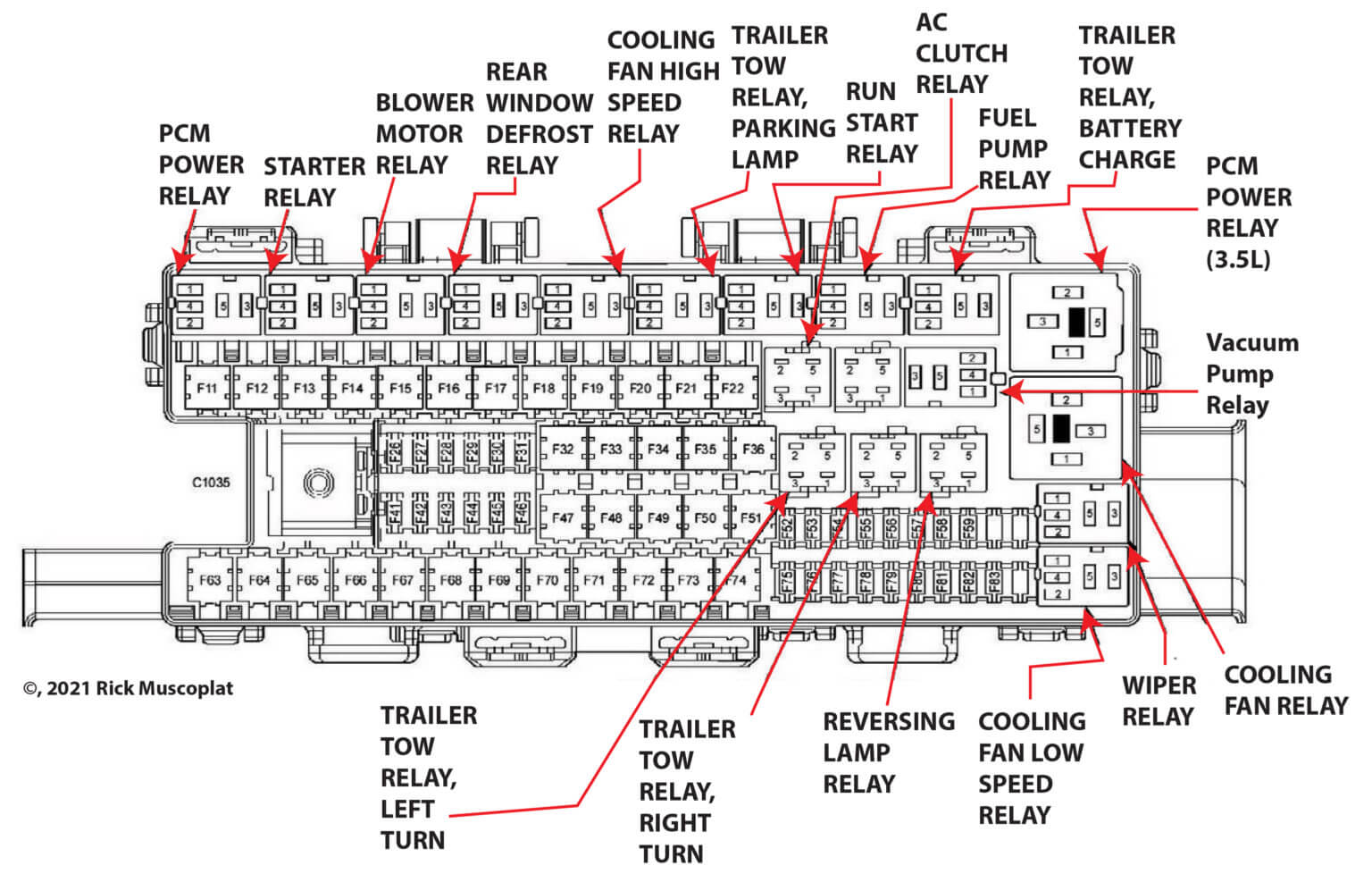
The passenger side fuse box, often called the Battery Junction Box (BJB) in Ford terminology, is a critical component of the F150's electrical system. It's typically located under the passenger side dashboard, sometimes behind a trim panel that needs to be removed. The exact location may vary slightly depending on the specific cab configuration (Regular Cab, SuperCab, or SuperCrew).
Key specifications you need to pay attention to when using the diagram include:
- Fuse Amperage Rating: Measured in Amperes (A), this indicates the maximum current a fuse can handle before blowing. Always replace a blown fuse with one of the same amperage rating. Using a higher amperage fuse can damage the circuit it's protecting.
- Circuit Description: The diagram lists what each fuse protects. This helps you pinpoint the source of the problem when a fuse blows. For example, you might see "Radio," "Power Windows," or "Fuel Pump."
- Relay Locations: Some circuits use relays, which are electrically operated switches that control higher-current circuits. The diagram will indicate the location of these relays within the fuse box.
Main parts of the fuse box itself include:
- Fuses: The protective devices that blow when a circuit is overloaded. Common fuse types include blade fuses (ATO, mini-ATO, and Maxi fuses).
- Relays: Electrically operated switches that control higher-current circuits, often triggered by low-current signals from the vehicle's computer.
- Connector Blocks: These provide connection points for wiring harnesses, allowing for easy connection and disconnection of electrical components.
Symbols – Decoding the Diagram
Understanding the symbols on the fuse box diagram is key to interpreting it correctly. Here's a breakdown:
- Lines: Solid lines represent electrical wires. Thicker lines may indicate wires that carry more current. Dashed lines can indicate a ground connection or a less direct connection.
- Colors: Wire colors are typically indicated on the diagram. This helps you trace wires in the vehicle. Common colors include red (power), black (ground), and various other colors for signal wires.
- Fuse Symbol: Usually a rectangle with a zigzag line inside, representing the fuse element.
- Relay Symbol: Typically a square with a coil symbol inside, representing the relay coil, and a switch symbol indicating the relay contacts.
- Ground Symbol: A symbol resembling an upside-down tree or a series of decreasing horizontal lines, indicating a connection to the vehicle's chassis ground.
Color coding is important. For example, a red wire usually indicates a power wire, while a black wire indicates a ground wire. Knowing these conventions can help you quickly identify the function of a wire.
How It Works: The Fuse Box in Action
The fuse box acts as a central distribution point for electrical power within the vehicle. Power from the battery flows into the fuse box, where it is then distributed to various circuits through fuses and relays. Each fuse protects a specific circuit from overcurrent conditions. If the current in a circuit exceeds the fuse's amperage rating, the fuse blows, interrupting the flow of current and preventing damage to the circuit components.
Think of it like this: each fuse is a weak link in the chain. If something goes wrong and too much current flows through a circuit, the fuse blows *before* it can damage something more expensive, like the radio, power window motor, or even the vehicle's computer.
Relays are used to control high-current circuits with low-current signals. For example, the headlight circuit may use a relay to switch on the headlights. The headlight switch in the cabin sends a low-current signal to the relay, which then closes the high-current circuit to power the headlights.
Real-World Use: Troubleshooting Basic Issues
Here's how to use the fuse box diagram to troubleshoot common problems:
- Identify the Problem: Determine which system is not working (e.g., radio, power windows, headlights).
- Consult the Diagram: Locate the fuse associated with the affected system on the passenger side fuse box diagram.
- Inspect the Fuse: Remove the fuse and visually inspect it. A blown fuse will have a broken filament inside. You can also use a multimeter to check for continuity. If there's no continuity, the fuse is blown.
- Replace the Fuse: Replace the blown fuse with a new fuse of the same amperage rating.
- Test the System: Turn on the system to see if it now works.
- If the Fuse Blows Again: If the new fuse blows immediately or shortly after being replaced, there is a short circuit or overload in the circuit. This requires further investigation to identify and repair the cause of the problem.
If a fuse keeps blowing, don't just keep replacing it with a higher amperage fuse. This is extremely dangerous and can lead to overheating and electrical fires. Instead, diagnose the underlying problem, which could be a short circuit, damaged wiring, or a faulty component.
Safety First!
Working with automotive electrical systems can be dangerous. Here are some important safety precautions:
- Disconnect the Battery: Before working on any electrical components, disconnect the negative (-) battery cable to prevent accidental shorts and electrical shocks.
- Use Proper Tools: Use insulated tools designed for automotive electrical work.
- Never Bypass Fuses: Never replace a fuse with a wire or other conductive material. This eliminates the circuit protection and can lead to serious damage or fire.
- Be Careful with High-Current Circuits: Some circuits, such as the starter motor circuit, carry very high current. Be extremely cautious when working with these circuits.
- If in Doubt, Seek Professional Help: If you are not comfortable working on automotive electrical systems, consult a qualified mechanic.
Remember that some components, like the airbag system, can be extremely dangerous if handled improperly. If you suspect a problem with the airbag system, it's always best to seek professional help.
Warning: Working with automotive electrical systems can be hazardous. Always disconnect the battery before working on any electrical components. Never bypass fuses. If you are not comfortable working on electrical systems, seek professional help.
By understanding the 2011 Ford F150 passenger side fuse box diagram, you'll be well-equipped to diagnose and repair electrical problems, add aftermarket accessories, and gain a deeper understanding of your truck's electrical system. This knowledge empowers you to tackle DIY projects with confidence and save money on costly repairs.
We have the full 2011 Ford F150 passenger side fuse box diagram available for download. This document provides a detailed overview of each fuse and relay, making it an invaluable resource for any F150 owner. Contact us to receive the file!