2011 Ford F150 Radio Wiring Harness Diagram
Alright, let's dive into the radio wiring harness diagram for the 2011 Ford F-150. This isn't just some abstract piece of paper; it's the key to unlocking a whole range of possibilities for your truck's audio system. Whether you're troubleshooting a faulty speaker, upgrading to a new head unit, installing an aftermarket amplifier, or simply trying to understand how all the pieces fit together, this diagram is your best friend. Think of it as the Rosetta Stone for your F-150's audio system.
Purpose: Why This Diagram Matters
Understanding your radio wiring harness is crucial for several reasons:
- Repairs: Identifying and fixing broken or damaged wires. A frayed wire can lead to poor sound quality, intermittent signal loss, or even complete system failure.
- Upgrades: Safely installing aftermarket head units, amplifiers, speakers, or subwoofers. Proper wiring ensures compatibility and prevents electrical damage.
- Diagnostics: Tracing electrical issues within the audio system. Is power reaching the radio? Are the speakers properly connected? The diagram helps you isolate the problem.
- Customization: Modifying the audio system to your specific needs, such as adding Bluetooth connectivity, a backup camera, or steering wheel control integration.
- Learning: Gaining a deeper understanding of your vehicle's electrical system. Knowing how the audio system is wired can empower you to tackle other DIY projects.
Key Specs and Main Parts
The 2011 Ford F-150 radio wiring harness is a complex system with numerous wires, each serving a specific function. Here's a breakdown of the main components and specs to keep in mind:
- Head Unit Connector(s): This is the primary connection point between the radio (head unit) and the vehicle's electrical system. It typically involves one or more multi-pin connectors.
- Speaker Wires: These wires connect the head unit to the individual speakers (front left, front right, rear left, rear right). Each speaker has a positive (+) and negative (-) wire.
- Power Wires:
- +12V Constant (Battery): Provides continuous power to the radio, even when the ignition is off, for memory retention (presets, clock settings).
- +12V Switched (Ignition): Supplies power to the radio when the ignition is turned on.
- Ground: Completes the electrical circuit, providing a return path for the current. Usually connected to the vehicle's chassis.
- Antenna Connection: Connects the radio to the vehicle's antenna, allowing it to receive radio signals. Usually a standard coaxial connector.
- Remote Turn-On (Amplifier Turn-On): A wire that signals an aftermarket amplifier to turn on when the radio is powered on. This is crucial for preventing the amp from draining the battery when not in use.
- Illumination Wire: Diminishes the radio display when the vehicle's headlights are turned on, reducing glare at night.
- Steering Wheel Control Wires (if equipped): These wires allow the steering wheel controls to interact with the radio, enabling you to adjust volume, change tracks, and answer calls without taking your hands off the wheel. Requires an adapter for aftermarket radios.
- Factory Amplifier (if equipped): Some F-150s came with a factory amplifier, which requires a different wiring configuration. The diagram will show the connections between the head unit and the amplifier.
Symbols: Deciphering the Diagram
A wiring diagram uses standard symbols to represent electrical components and connections. Understanding these symbols is essential for accurate interpretation.
- Lines: Represent wires. The thickness of the line may indicate the wire gauge (thicker lines for higher current).
- Colors: Each wire is assigned a specific color code (e.g., red for +12V, black for ground). These color codes are critical for identifying the correct wires.
- Circles/Dots: Indicate wire splices or connections. A filled circle typically represents a permanent connection, while an open circle may represent a removable connector.
- Rectangles: Represent components like fuses, relays, or connectors.
- Ground Symbol: Represents a connection to the vehicle's chassis, providing a path for the current to return to the battery.
- Component Symbols: Symbols represent various electrical components (resistors, capacitors, diodes, etc.). These are less common in basic radio wiring diagrams but may appear in more complex schematics.
- Abbreviations: Common abbreviations include GND (ground), PWR (power), ACC (accessory), SPK (speaker), and ANT (antenna).
Pay close attention to the wire colors. Ford uses a consistent color-coding system, but variations can occur between model years and trim levels. The wiring diagram will specify the exact color code for your 2011 F-150.
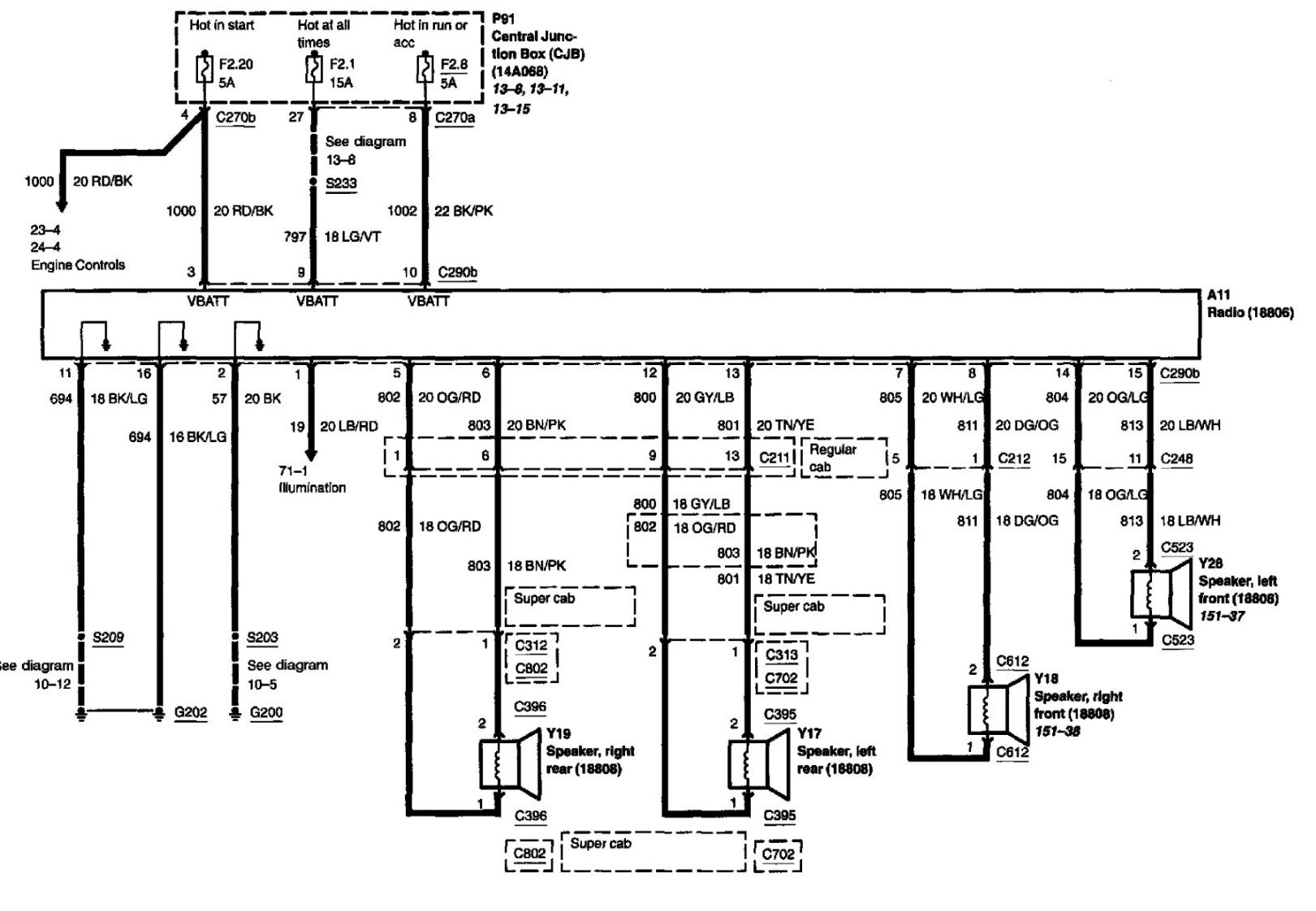
How It Works: Tracing the Circuit
The 2011 F-150 radio wiring harness essentially acts as the central nervous system for your truck's audio. Power flows from the battery to the head unit through the +12V constant and +12V switched wires. The head unit then processes audio signals from various sources (radio, CD, Bluetooth, etc.) and sends them to the speakers via the speaker wires. The antenna receives radio signals and passes them to the head unit for processing. Any additional components, such as amplifiers or steering wheel control adapters, are integrated into this network through specific wiring connections.
Tracing the circuit involves following the wires from the power source to the head unit, then from the head unit to the speakers. The diagram will show you the path of each wire, including any intermediate connectors or components. By carefully tracing the circuit, you can identify any breaks or shorts that may be causing problems.
For instance, if a particular speaker isn't working, you can use the diagram to trace the speaker wires back to the head unit. Check for loose connections, damaged wires, or a blown fuse along the way. If the problem isn't obvious, you can use a multimeter (a device that measures voltage, current, and resistance) to test the continuity of the wires.
Real-World Use: Basic Troubleshooting Tips
Here are some common troubleshooting scenarios and how the wiring diagram can help:
- No Power to the Radio: Use the diagram to check the +12V constant and +12V switched wires. Verify that the fuses associated with these circuits are not blown. Use a multimeter to confirm that voltage is present at the head unit connector.
- One Speaker Not Working: Trace the speaker wires for the affected speaker back to the head unit. Check for loose connections or damaged wires. Test the speaker itself to rule out a faulty speaker.
- Intermittent Sound: This can be caused by loose connections or frayed wires. Use the diagram to inspect all the wiring connections for the audio system. Pay particular attention to areas where the wires may be rubbing against the vehicle's metal frame.
- Aftermarket Radio Installation Issues: The wiring diagram is essential for connecting the aftermarket radio to the vehicle's electrical system. Ensure that you are connecting the correct wires to the corresponding wires on the aftermarket radio harness adapter.
Safety: Proceed with Caution!
Working with electrical systems can be dangerous. Always disconnect the negative terminal of the battery before working on the radio wiring harness. This will prevent accidental shorts and electrical shocks. The +12V constant wire carries significant current, so avoid touching it with any metal objects while the battery is connected. Use insulated tools and wear safety glasses to protect yourself from potential hazards.
Remember, if you're not comfortable working with electrical systems, it's best to consult a qualified professional. Messing with the wrong wires can damage your vehicle's electrical system or even cause a fire. Be very careful when working with the wiring for the airbags, as they can deploy unexpectedly if mishandled. These are usually a yellow harness and shouldn't be messed with unless you are properly trained.
You should also be aware of the factory amplifier if your F-150 is equipped with one. Bypassing or replacing the factory amplifier requires specific wiring knowledge and may require an amplifier integration interface. Consult the wiring diagram to understand how the amplifier is connected and what modifications are necessary.
Now that we've covered the basics, you're ready to put this knowledge to use. We have the complete 2011 Ford F-150 radio wiring harness diagram available for download. This detailed diagram will provide you with the specific wire colors, connector locations, and circuit paths for your truck's audio system. Use it responsibly and always prioritize safety.