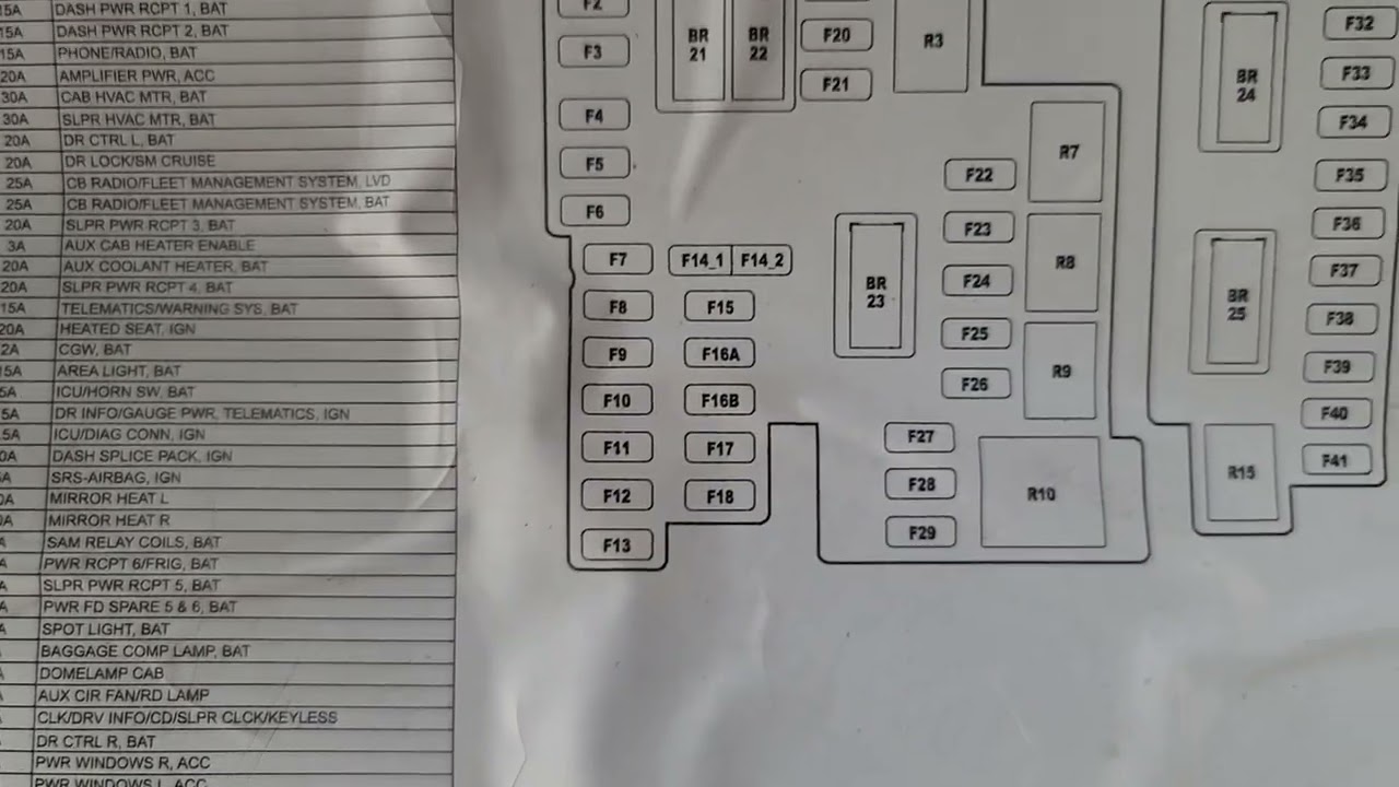
2011 Freightliner Cascadia Fuse Box Diagram
The 2011 Freightliner Cascadia is a workhorse, and understanding its electrical system is crucial for maintenance, repairs, and even simple modifications. A critical tool in that understanding is the fuse box diagram. This article will guide you through deciphering the diagram for your 2011 Cascadia, empowering you to diagnose electrical issues efficiently and safely. We'll cover everything from the diagram's purpose to practical troubleshooting tips.
Purpose of the Fuse Box Diagram
Why bother with a fuse box diagram? Several reasons make it indispensable:
- Troubleshooting Electrical Problems: When an electrical component fails (lights, wipers, etc.), the first thing to check is often the fuse. The diagram tells you exactly which fuse corresponds to which component.
- Preventing Catastrophic Damage: Replacing a blown fuse with one of a higher amperage can overload the circuit and potentially cause a fire. The diagram ensures you use the correct amperage fuse.
- Making Safe Modifications: Adding aftermarket accessories (lights, radios, etc.) requires tapping into the electrical system. Knowing the function of each circuit helps you make safe and informed choices.
- General Understanding: Simply studying the diagram provides valuable insight into how your truck's electrical system is structured and protected.
Think of the fuse box as the circuit breaker panel in your house – it protects the wiring and components from overcurrents. The diagram is your key to understanding that panel.
Key Specs and Main Parts of the 2011 Cascadia Fuse Box
The 2011 Cascadia typically has multiple fuse boxes, each serving different sections of the vehicle's electrical system. The primary fuse box is usually located under the dash, often on the driver's side. Some models may also have a fuse box in the engine compartment or sleeper area. Each fuse box will have its own corresponding diagram. Finding the right diagram for the *specific* fuse box you are working on is paramount. These fuse box locations may shift slightly based on your truck's particular configuration, so *always consult your owner's manual* first.
Key components within the fuse box include:
- Fuses: These are sacrificial devices that protect circuits from overcurrents. They contain a thin wire that melts and breaks the circuit when the current exceeds the fuse's rated amperage.
- Relays: These are electromechanical switches that allow a low-current circuit to control a high-current circuit. They are used to switch on things like headlights, starters, and other high-power devices.
- Circuit Breakers: Similar to fuses, but they automatically reset after a short period (though they might need manual resetting sometimes). They're less common in fuse boxes but may be used for certain high-demand circuits.
- Bus Bars: These are conductive strips that distribute power to multiple fuses and relays.
- Connectors: These provide a secure and reliable connection for wires entering and exiting the fuse box.
Understanding the physical layout of the fuse box is as important as understanding the diagram itself. Take some time to familiarize yourself with the location of each component.
Understanding Fuse Box Diagram Symbols
Fuse box diagrams use a standardized set of symbols, lines, and colors to convey information efficiently. Here's a breakdown of common symbols:
Fuse Symbols
The most common symbol for a fuse is a zigzag line enclosed in a rectangular box. Sometimes it's represented by a single, straight line within the box. The amperage rating (e.g., 10A, 20A) is usually printed next to the symbol. Remember that using the wrong amperage fuse can be dangerous!
Relay Symbols
Relays are typically represented by a square or rectangle with internal symbols indicating the coil and the switch contacts. The diagram may also include numbers or letters indicating the terminal numbers of the relay.
Wire Colors
Wire colors are indicated using abbreviations, such as: BLU (Blue), RED (Red), GRN (Green), BLK (Black), WHT (White), YEL (Yellow), and so on. Understanding these color codes is crucial for tracing wires and identifying circuits.
Line Thickness
The thickness of a line in the diagram can sometimes indicate the wire gauge (thickness) of the corresponding wire. Thicker lines generally represent heavier gauge wires capable of carrying higher currents.
Icons
Many diagrams will use icons to represent specific components, such as headlights, windshield wipers, or the horn. These icons provide a quick visual reference to the circuit's function. For example, a headlight icon will naturally identify the fuse for the headlights.
Key takeaway: Pay close attention to the legend or key provided with the diagram. This will explain any non-standard symbols or abbreviations used.
How It Works: Electrical Protection
The fuse box is designed to protect your truck's electrical system from overcurrents. When a fault occurs (e.g., a short circuit), the current flowing through the affected circuit increases dramatically. This excessive current can damage wiring, components, and even cause a fire. The fuse, being the weakest link in the circuit, is designed to blow (melt) before any significant damage occurs. This breaks the circuit and prevents further current flow.
Relays function as remote-controlled switches. A small current applied to the relay's coil energizes it, which then closes (or opens) the switch contacts. This allows a low-current circuit (e.g., a dashboard switch) to control a high-current circuit (e.g., the starter motor). Relays are essential for managing high-power loads without requiring heavy-duty switches on the dashboard.
Understanding the flow of electricity is crucial. From the battery, electricity travels through the wiring harness, passing through fuses and relays as needed, and eventually reaching the electrical components. The fuse box is strategically placed in this path to provide protection where it's needed most.
Real-World Use: Basic Troubleshooting
Here’s a basic troubleshooting scenario:
- Symptom: Your headlights are not working.
- Step 1: Consult the fuse box diagram to identify the fuse(s) for the headlights.
- Step 2: Locate the headlight fuse(s) in the fuse box.
- Step 3: Visually inspect the fuse(s). A blown fuse will typically have a broken filament.
- Step 4: Use a multimeter to test the fuse(s) for continuity. A good fuse will have continuity (near-zero resistance).
- Step 5: If the fuse is blown, replace it with a fuse of the exact same amperage rating.
- Step 6: If the new fuse blows immediately, there is a short circuit in the headlight circuit. Further investigation is required. This might involve checking the wiring harness for damage or testing the headlight assembly itself.
Important: Never replace a blown fuse with one of a higher amperage rating. This is a fire hazard. Always use the correct amperage fuse as specified in the diagram.
Safety Considerations
Working with automotive electrical systems can be dangerous. Here are some safety precautions:
- Disconnect the Battery: Before working on any electrical component, disconnect the negative terminal of the battery to prevent accidental short circuits.
- Use Proper Tools: Use insulated tools designed for automotive electrical work.
- Avoid Water: Never work on electrical systems in wet conditions.
- Identify High-Risk Components: The starter motor circuit, alternator circuit, and battery charging circuit are high-current circuits that can be very dangerous if mishandled. Exercise extreme caution when working on these circuits.
- Read the Diagram Carefully: Understand the function of each circuit before making any modifications or repairs.
Warning: The starter motor circuit carries a very high current. Accidental short circuits in this circuit can cause severe burns and even explosions.
We have access to the 2011 Freightliner Cascadia fuse box diagram file, and it is available for you to download for closer inspection and assistance with your project.